
A01 Boards and Some 3D Prints
Over the weekend I assembled two of the A01 boards with some successes and some errors that require board updates. I also managed to get a basic firmware created to take JSON objects from a bluetooth connection.
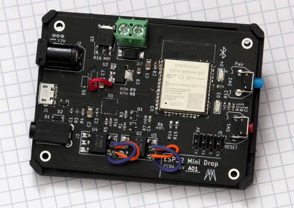
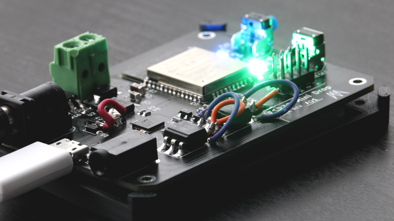
The assembly process went well, the parts were not too hard to solder by hand with the help of a microscope and a hot air gun for the QFN package. I might consider increasing the size of the passive components from 0603 to 0805 or even higher for easier hand assembly. As you can see there were some jumper wires needed to get things working.
No connection between D6 and U2 pin 3
The red jumper in the middle of the board is to solve a no connection between the diode D6 and the input of the voltage regulator U2. The diode had the right voltage (12V) on its cathode, but the trace connecting that to the linear regulator didn’t connect for some reason. There wasn’t an apparent fault with the board, and I partially assembled another board that repeated the problem.
To address this, I added a pour of copper to the A02 revision to connect all the shared nets with a solid pad of copper.
Reversed Collector and Emitter on optoisolator
The other jumper wires are switching the collector and emitter on the BJT within the optoisolator. This was an error on the schematic that has been fixed for A02 boards.
Programming using USB to UART Bridge
The USB to UART bridge works for transmitting and recieving serial communication between the computer and the ESP32, however the self reseting and boot mode selection isn’t working. I need to spend some time figuring out why and how to fix it.
Another idea is to do a cost benefit analysis on removing the USB to UART bridge, and instead using the manual programming header. Or a middle ground and having the pair button be tied to GPIO0 so you can put the device in programming mode without removing the PCB.
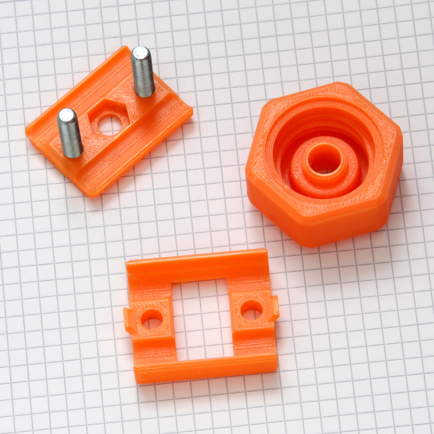
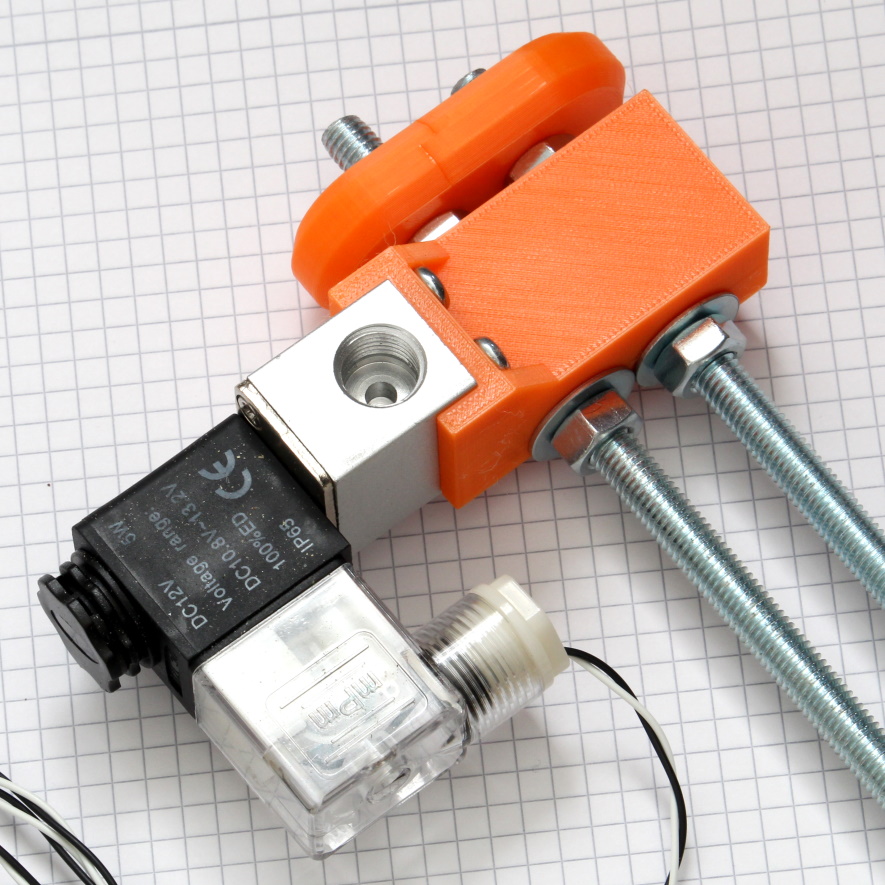
3D Printing
There were some successes and failures when 3D printing some of the parts. I am struggling with realizing just how small the parts are, so I need to make them larger than what looks right in CAD.
The bottle adapter came out great, it seals well enough for a printed piece. I will need some brass fittings to mate with the solenoid, as the printed fittings break apart when trying to install.
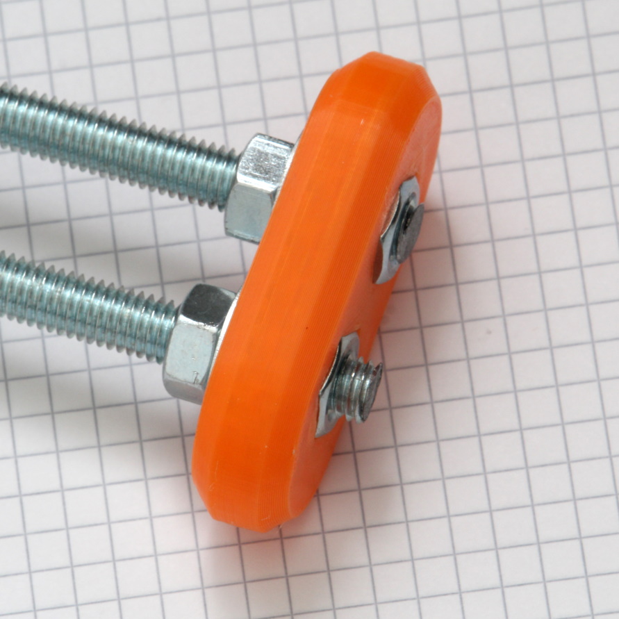
The rod ends needed some rework to allow for captive nuts. When the two rods are twisted it loosens the nuts and the whole assembly starts coming undone. The new rod ends help to minimize any twisting on the two rods.
What’s next
I need to order some brass fittings to avoid the fragile 3D printed parts. I will need a 1/4” NPT male to male coupler, and a 1/4” NPT hose barb for 1/8” hoses.
I should invest in a logic analyzer so I can debug the RTS and DTR functionality.