Schematics
Below are the different parts of the schematic design for MiniDrop. They are broken up in different functional groups.
ESP32
The popular ESP32-WROOM-32D acts as the brains and communications controller for the system. This module includes both 2.4Ghz Wifi and Bluetooth 4.2 protocols. The microcontroller is a 40 Mhz 32-bit Xtensa MCU.
This module is programmed using the Arduino IDE over the UART 0 port. This tutorial from Nuno Santos goes into further detail on how to program these modules.
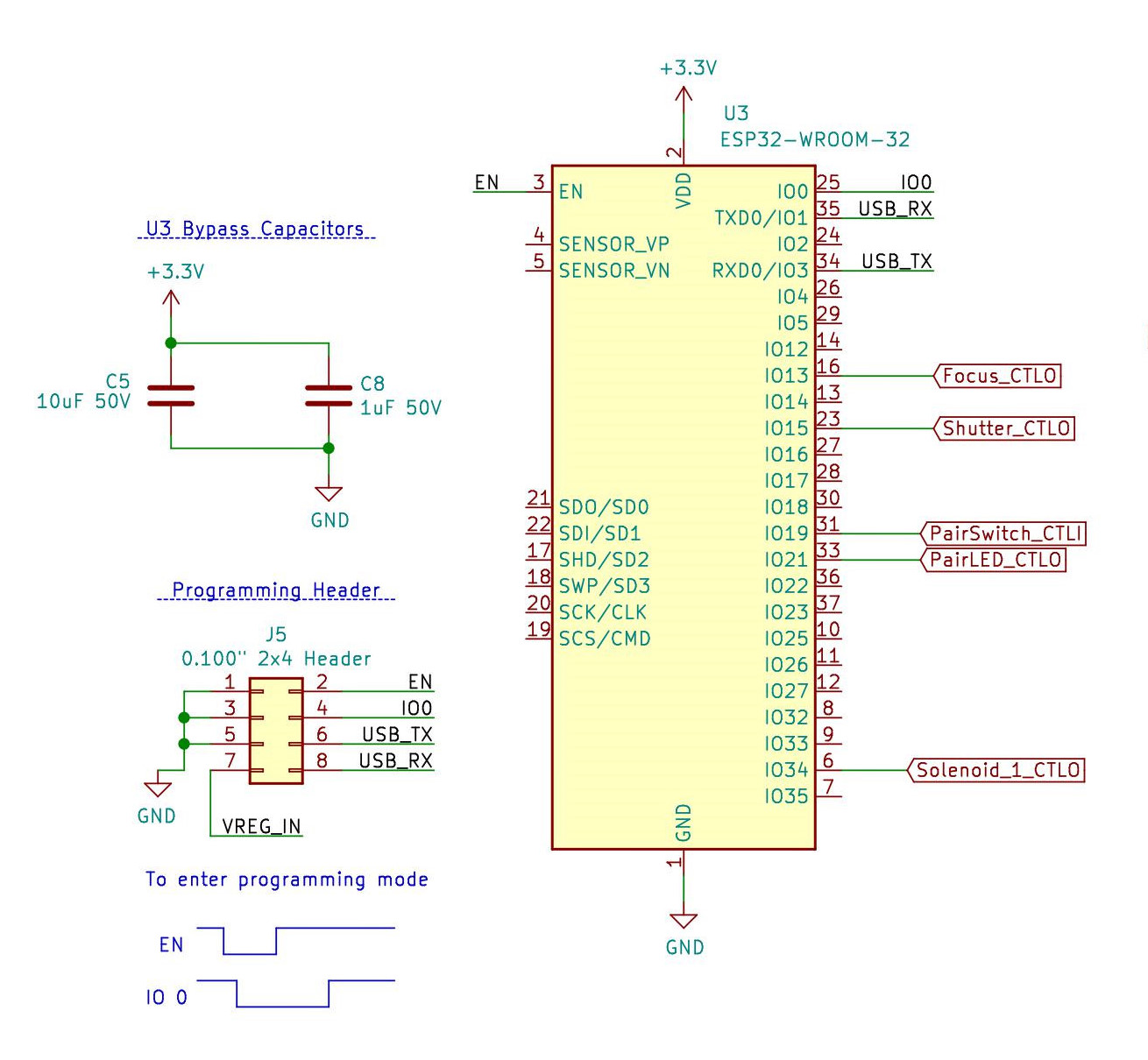
There are minimal supporting components, as almost all of the needed parts are on the module itself.
Solenoid Control
The method for controlling the 12V solenoid is a simple N-Channel Mosfet used as a low side driver: connecting the solenoid coil to ground, allowing current to flow and the magnetic field to be created.
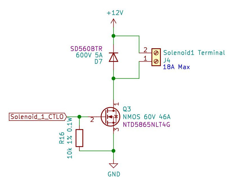 The flyback diode
 SD560BTR from SMC Diode Solutions is used to provide a path for current to flow back into the coil when the mosfet swtiches off, safely dissapating any stored energy when the solenoid is switched off.
To learn more about flyback diodes, check out this post from Electronics Hub.
The mosfet selection of NTD5865NLT4G from ON semiconductor is based on the power requirements of any possible 12V solenoid you could connect. In order to make sure the MOSFET can safely switch the solenoid, we need to have a large saftey margin. The Drain to Source Voltage of 60V allows us to safely have +12 V at the drain while the MOSFET is off. The max power dissapation of 71 Watts is well above the expected 6-8 Watts from most 12V solenoids.
Since the digital logic portion of the design is operating at 3.3V, a Gate Source Threshold voltage of 2 V allows the microcontroller to be able to switch the MOSFET on without needing an extra MOSFET to drive a higher gate voltage.
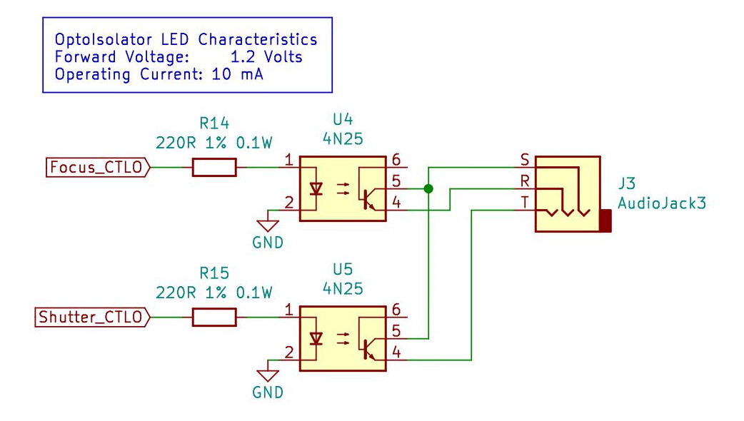
Camera Control
To be able to control the DSLR camera’s shutter and focus, optoisolators are used to bring the control signals to ground. These allow the camera to be electrically isolated from the 12V supply, helping to protect your expensive camera. The 3.5 mm audio jack might need to be adapted to your own camera. This post from Luk has a good overview of the major camera brands.
Otherwise, you can find adapter cables online to get the shutter release to a male 3.5 mm TRS connector.
The signal scheme may switch between Tip and Ring, so as to accommodate different camera models.
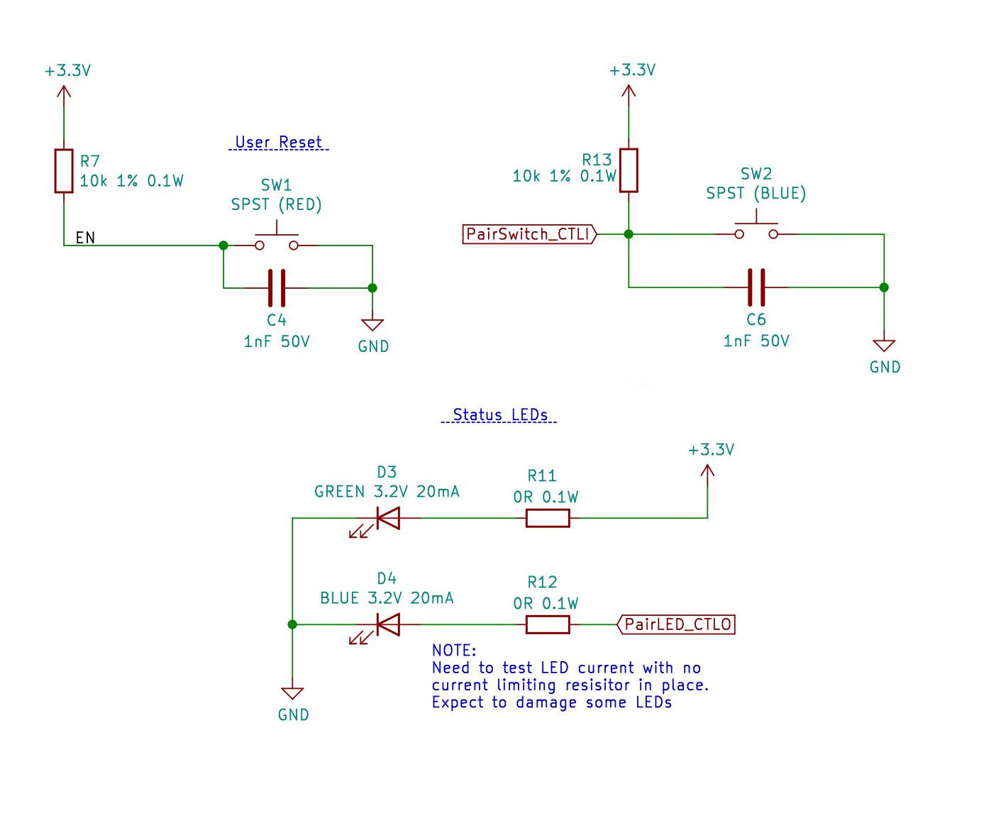
User Interface
The user interface one the device are two simple push button tactile switches with debounce capacitors, and two LEDs. One LED acting as a power indicator, and the other providing status information about the bluetooth function.
Note: The choice of LEDs will need some review, I’ve never used 3.2V LEDs on a 3.3V system. There is so little voltage difference, a current limiting resistor may not be needed.
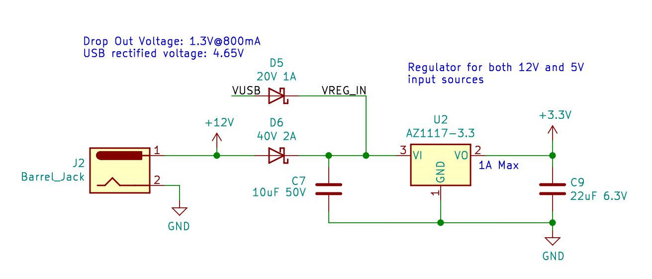
Power Supply
The power supply for this device should be an AC to DC converter rated at least 12V 1A. The voltage regulator was chosen for its current rating of maximum 1A (at 3.3V) which provides enough power for the microcontroller. The maximum input voltage is 15V and the drop out voltage is 4.6V.
The drop out voltage needs to taken into account since there is a shared bus for the regulator’s input. When the device is powered by an external USB to UART bridge, the diode D5 will have a voltage drop across it of at most 0.340 V, resulting in 4.66 V being fed into the voltage regulator.
When both the 12V DC power and the 5V DC power are present, the diode configuration prefers the 12V source, and no current should be sourced from or sunk into the 5V source.