Board Assembly
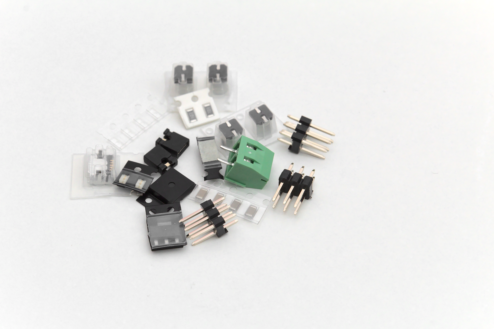
Once you’ve gotten your parts kit opened, it’s time to assemble your very own Micro Breadboard Power Supply!
The components and layout are identical between the solderless version and the integrated version, except for the lack of pin headers J3 & J4 on the integrated version.
If you are building your own right from the gerbers, or if you need to replace any of the components, I have tried my best to make sure there are plentiful replacements & alternatives available on the open parts market. Check the Bill of Materials for more information on what components were originally selected.
This board has a combination of both through hole and surface mount components.
Tools Needed
Before you begin soldering, make sure to gather your tools. It’s no fun to have your hands tied up and then realize the next tool you need is packed away somewhere (or worse, at the store!).
| Required | |
|---|---|
| Soldering Iron | If you have a soldering iron with a fine tip, that is preferred, however you can make do with a moderately sized tip. If it’s too big you might find difficulty with soldeing the surface mount components. I keep mine at 410 deg C for ROHS solder. |
| Solder | Make sure to have a solder that is thin enough. It should be less than 0.5 mm, with 0.3 mm being ideal. Too large and you’ll find it too easy to add too much. Large solder is useful for the through hole components. |
| Fine Tip Tweezers | SMD parts are small, make sure you have something that can pick them up and move them around. A second pair can help make fine adjustments to SMD placements. |
| Flux | Rosin based flux will help make sure all your solder joints are strong and hassle free. |
| Optional | |
|---|---|
| Vice | Something to hold down the PCB can be nice. There are a few different PCB vises out there, or try and DIY something that works. |
| Magnification | Ideally a stereo microscope or zoom camera, but a magnifying glass can be better than no magnifaction. Young eyes help too, but those can’t be bought. |
| Hot Air Station | This makes removing parts a snap if mistakes were made. It can also be used to position parts using the liquid solder’s surface tension. |
| Solder Paste | Using a hot air station with solder paste can make assembly a breeze. |
| Stencil | A piece of metal with holes cut out for where the solder paste can be scraped over. Most PCB fabricators offer stencils for a relatively small fee. |
Using a stencil? Jump to Instructions
Getting Started
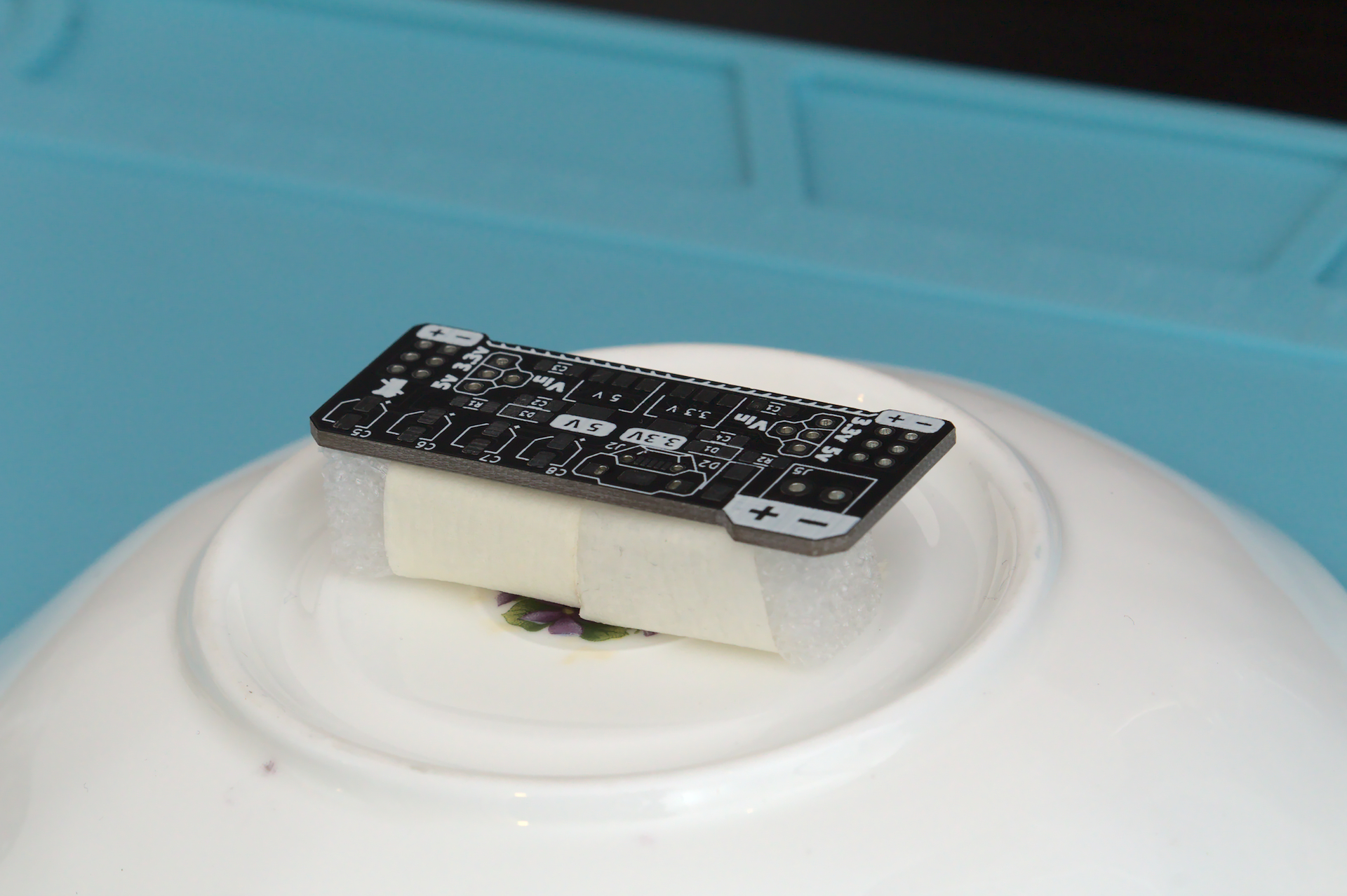
Now that you’ve got all the parts and tools, we can start hand soldering the SMD components.
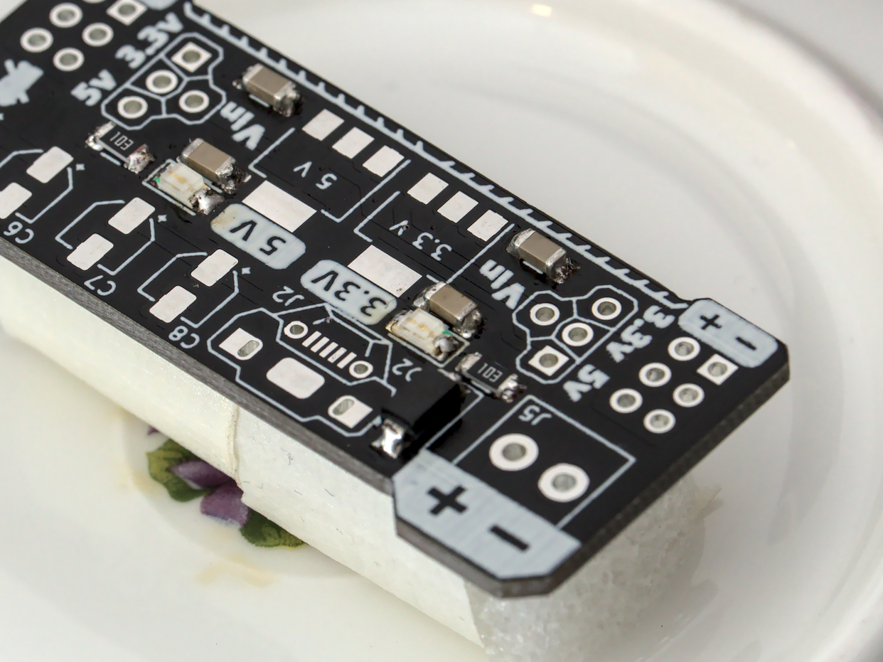
I threw together an improvised holder for the PCB using a tea saucer, masking tape, and closed cell foam. By wrapping the tape inside out, you can have a sticky band to attach the board to the stable tea saucer base. Rotating the suacer instead of the board helps keep things secured and easy to reach.
The general approach to soldering is to follow this method:
| 1 | attach some solder to one pad of the footprint |
| 2 | bring component relatively close to the footprint |
| 3 | touch the pad with solder and reflow with Iron |
| 4 | bring component onto footprint and align pads |
| 5 | remove iron and allow to cool |
| 6 | add solder to the remaining pads |
Use a hot air station to help remove mistakes and try again if it’s not working out.
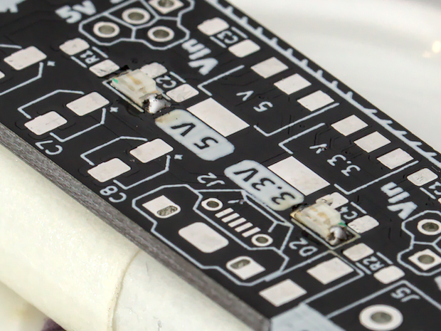
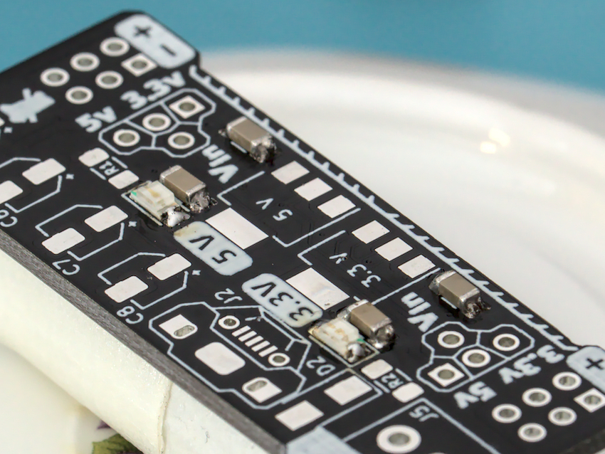
Start with the LEDs
| D1 D3 | EKINGLUX | E6C1206VGAC1UDA |
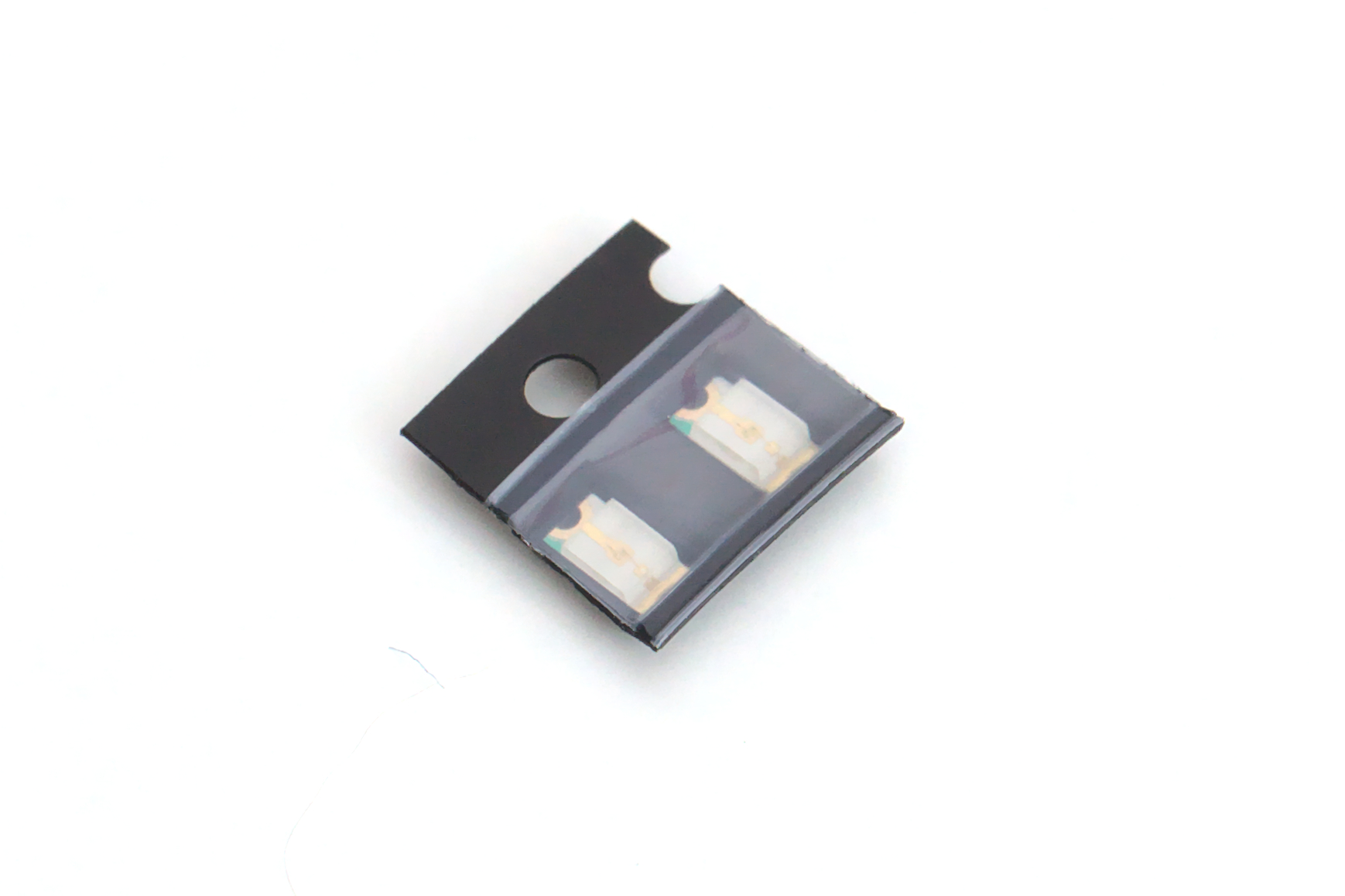
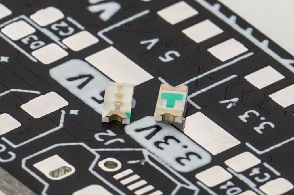
How to tell which way is which
When working with LEDs, it matters how you put them on. They will only work if the positive and negative terminals are correct. The footprints will have a bit of silkscreen around them that indicates where the negative terminal should be. The figure below shows how all the markings should line up.
If you have put them on backwards, they shouldn’t break when powered on. Just remove them and flip their orientation.
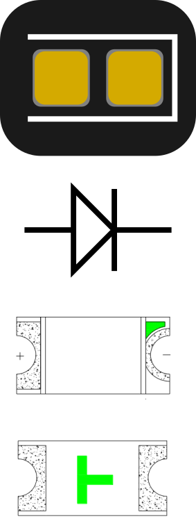
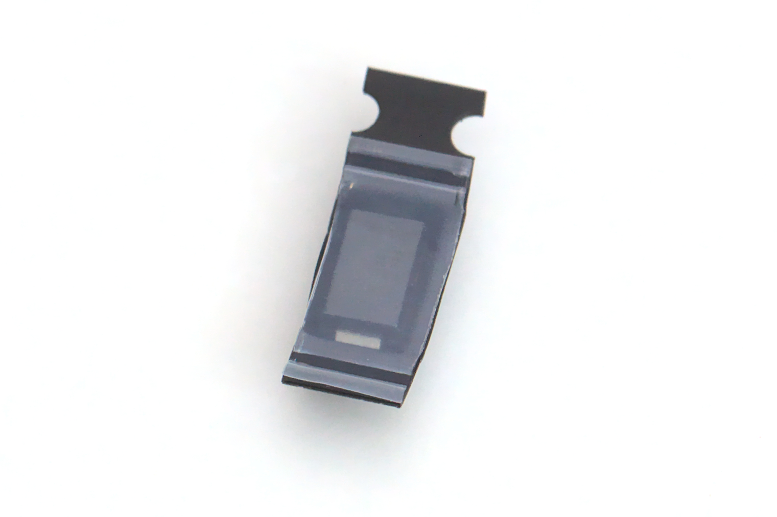
The datasheet for the LEDs have some more details:
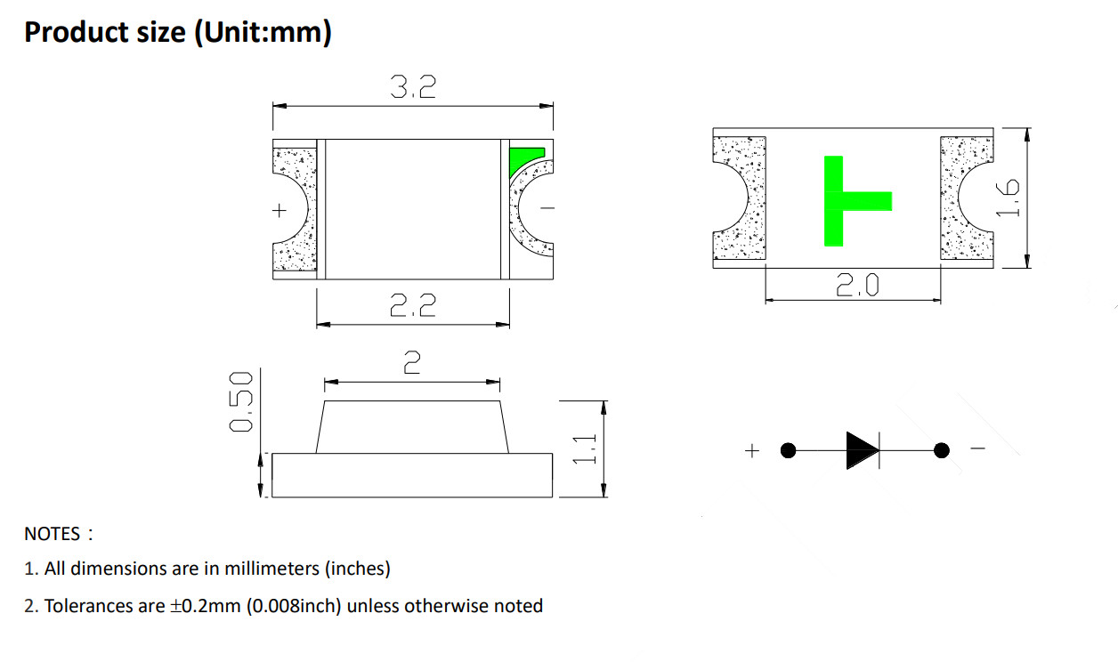
Here we can see that green marking shows which way to mount the component on the board.
Ceramic Capacitors
| C1 C2 C3 C4 | YAGEO | CC1206KKX7R9BB224 |
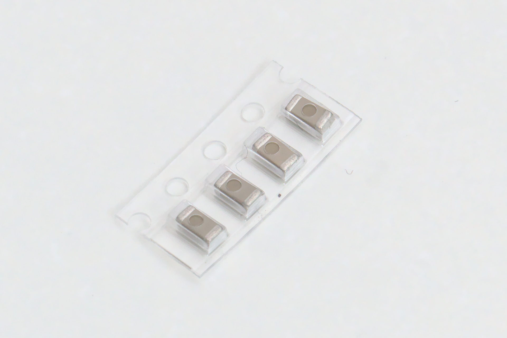
Next up are the 200nF ceramic capacitors C1, C2, C3, C4. These components don’t need a specifc orientation, so no need to worry about which way they are mounted.
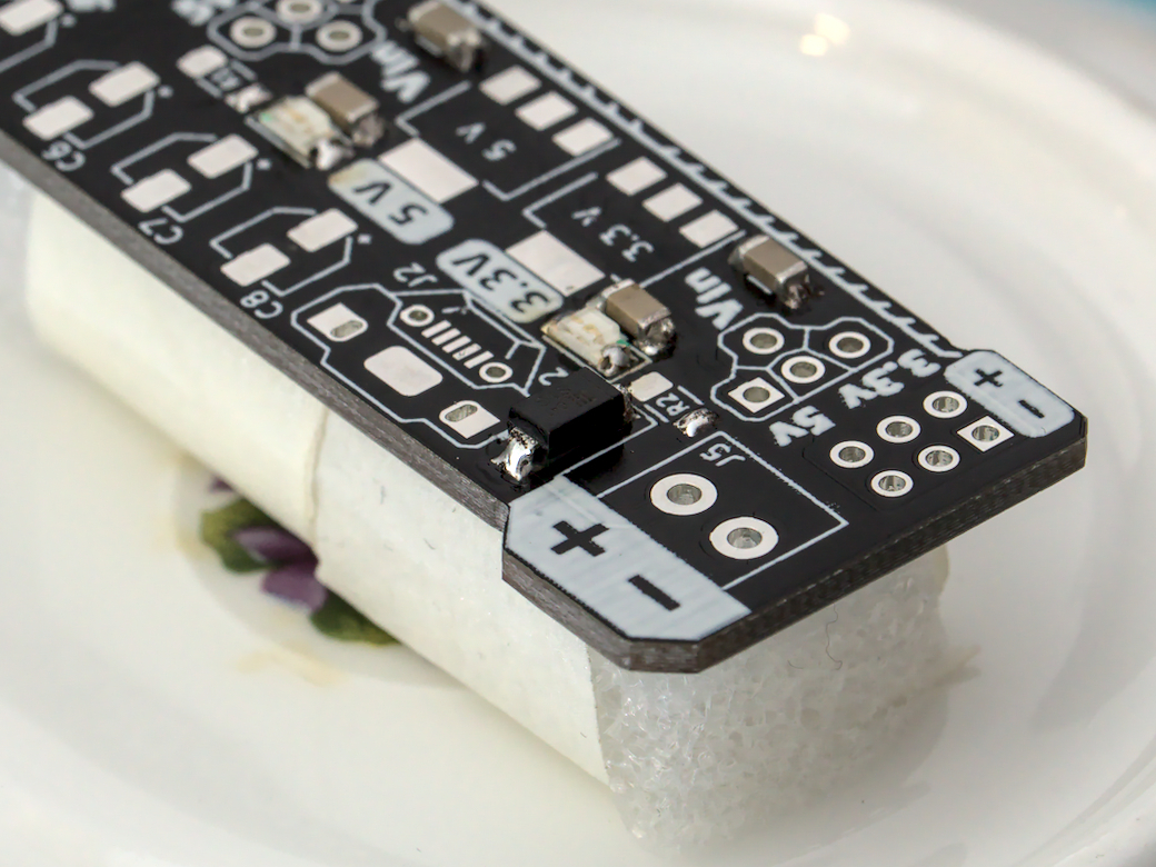
General Purpose Diode
| D2 | Diodes Incorporated | S1G-13-F |
Here is another orientation specific component. The diode D2 provides some reverse voltage protection from the screw terminal.
On the top of the component, a small line will indicate the negative terminal of the diode.
Resistors
| R1 R2 | YAGEO | RC1206JR-0710KL |
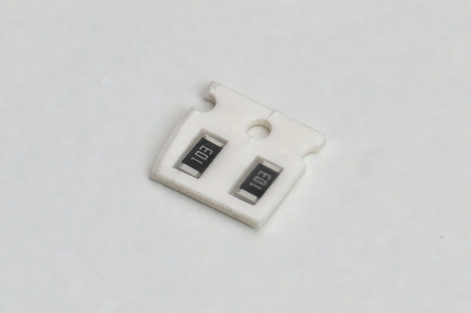
Like the ceramic capacitors, these can go on any way. They will be used to limit the current of the LEDs so they aren’t too bright.
Micro USB connector
| J2 | Korean Hroparts Elec | U-F-M5DD-Y-L |
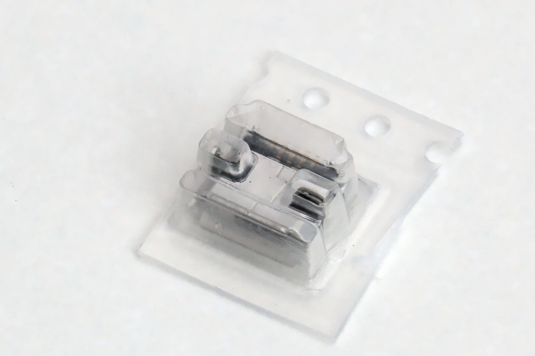
This component will be the hardest to hand solder to the board. If you have a hot air station, use that to mount this component.
To start, insert the component without any solder added to the footprint. Add a bit of solder to the larger mounting pads on the side. Use that to help fix the orientation so that the small interior pads are aligned properlly.
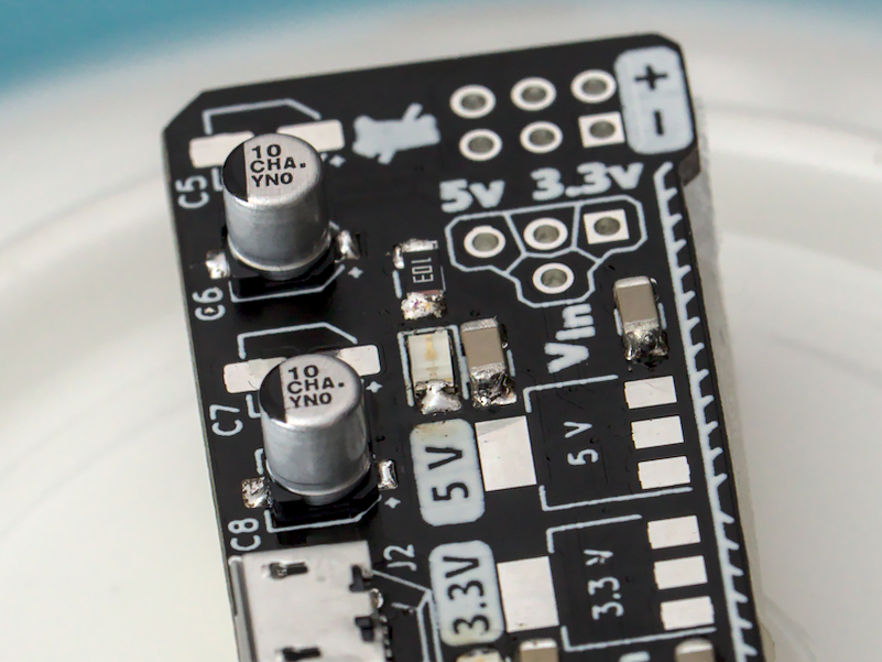
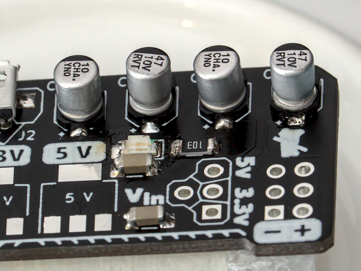
Electrolytic Capacitors
| C5 C7 | 10µF 16V | Panasonic | EEEHA1C100R |
| C6 C8 | 47µF 10V | ROQANG | RVT1A470M0405 |
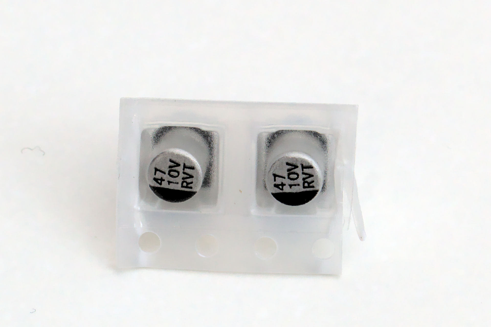
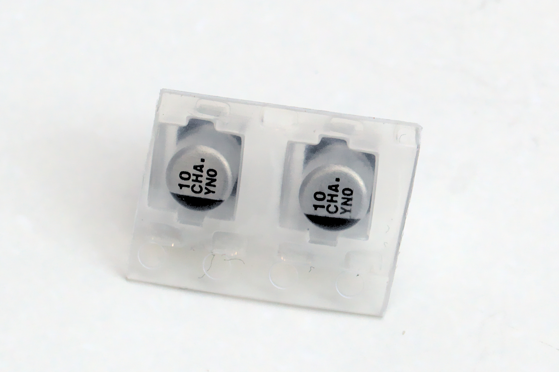
Check Orientation Make sure you check which way these parts are mounted. If incorrect, there is a strong likelyhood you will damage the parts.
Here the black bar represents the negative terminal. The footrpint will have a + symbol to indicate the positive terminal.
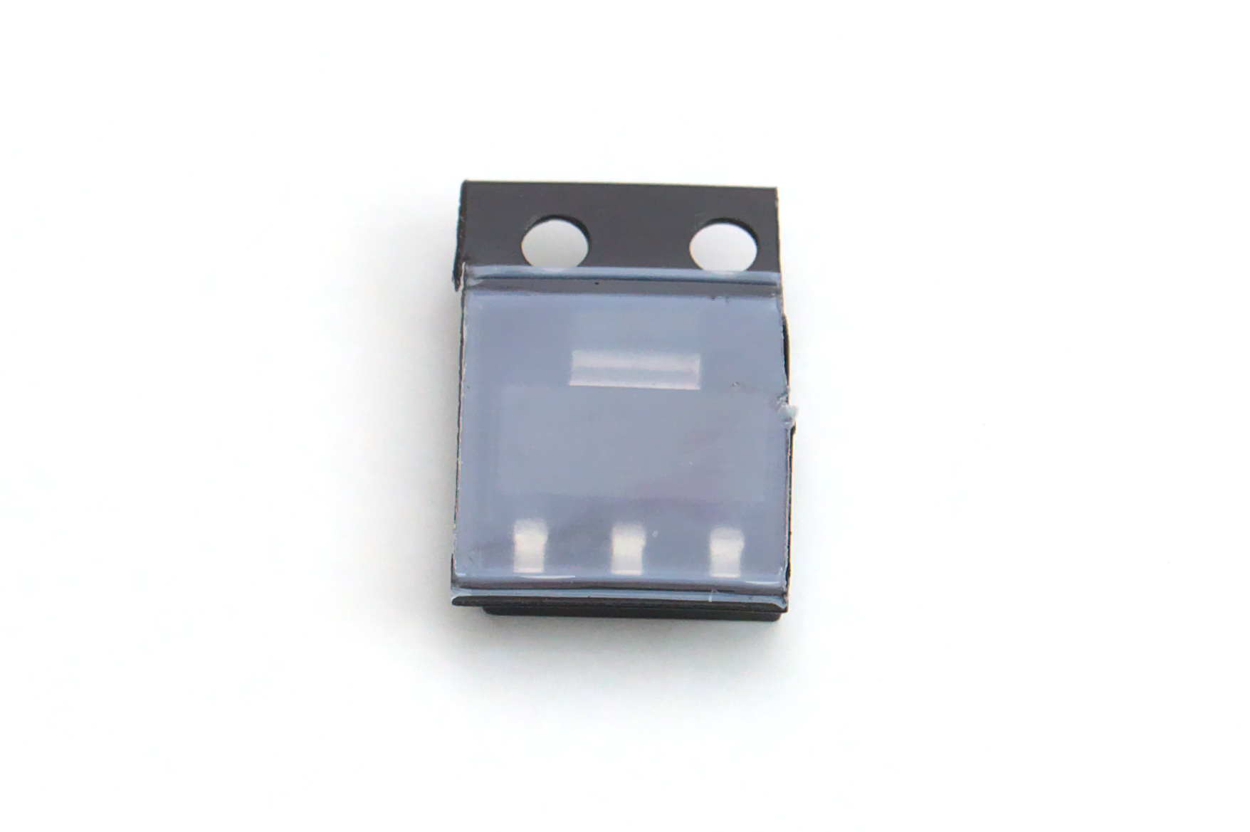
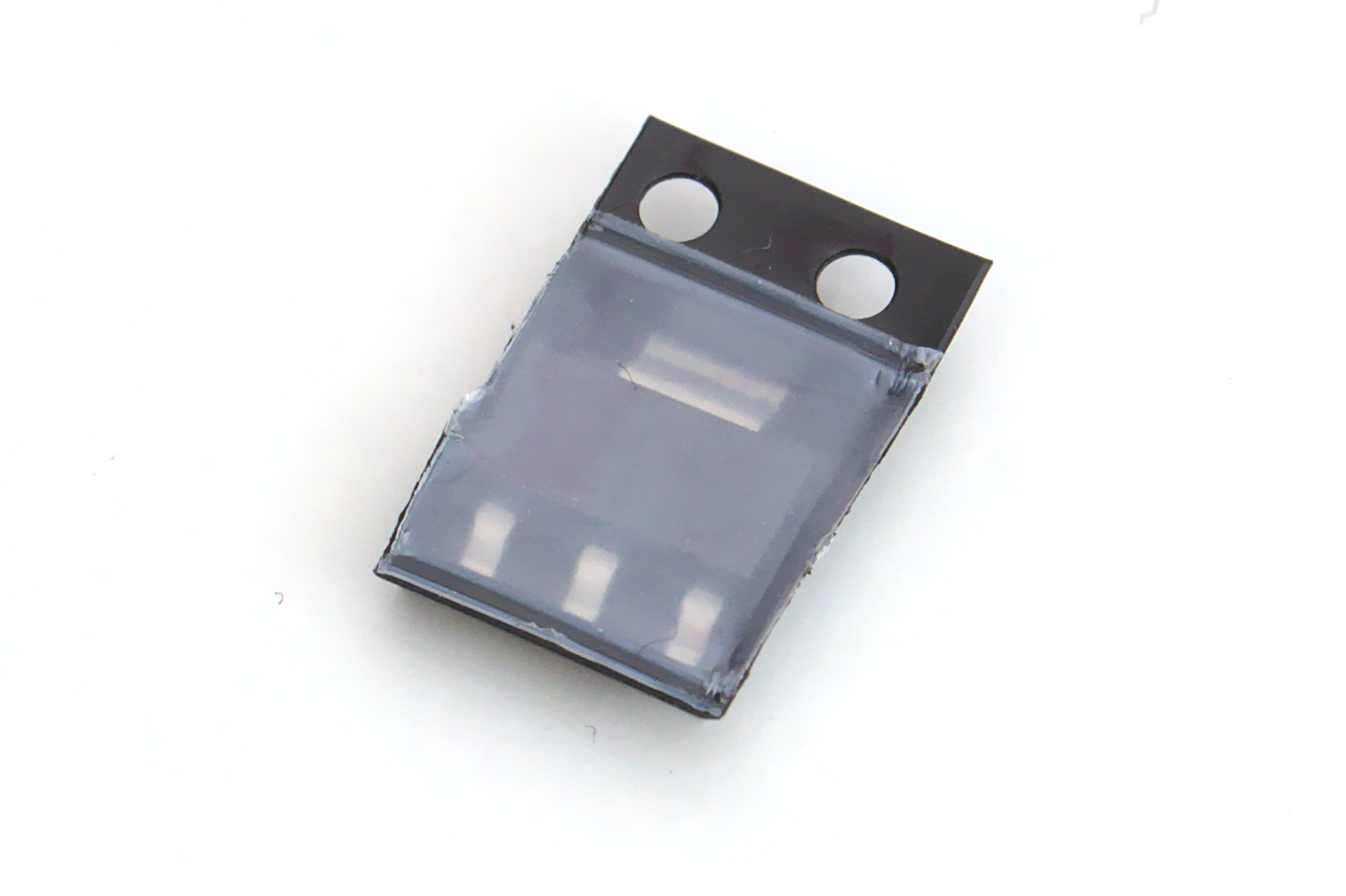
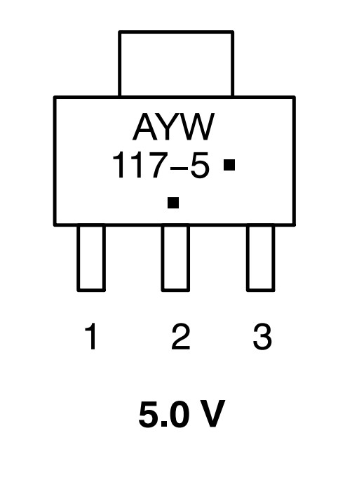
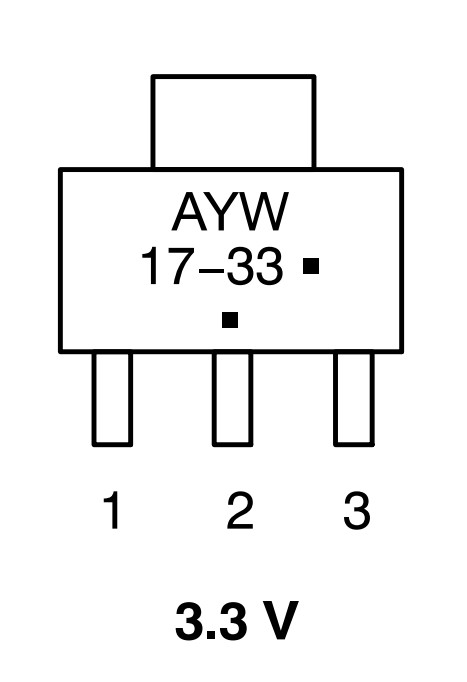
Voltage Regulators
These components have small lettering on them that can be used to tell them apart. If you have trouble reading them, you can try using the zoom on a digital camera and light directed at an angle to catch the lettering.
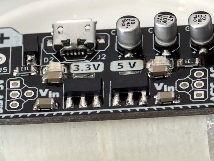
5 V
| U1 | ON Semiconductor | NCP1117ST50T3G |
3.3 V
| U3 | ON Semiconductor | NCP1117ST33T3G |
Header Pins
| J3 J4 | XFCN | PZ254V-12-6P |
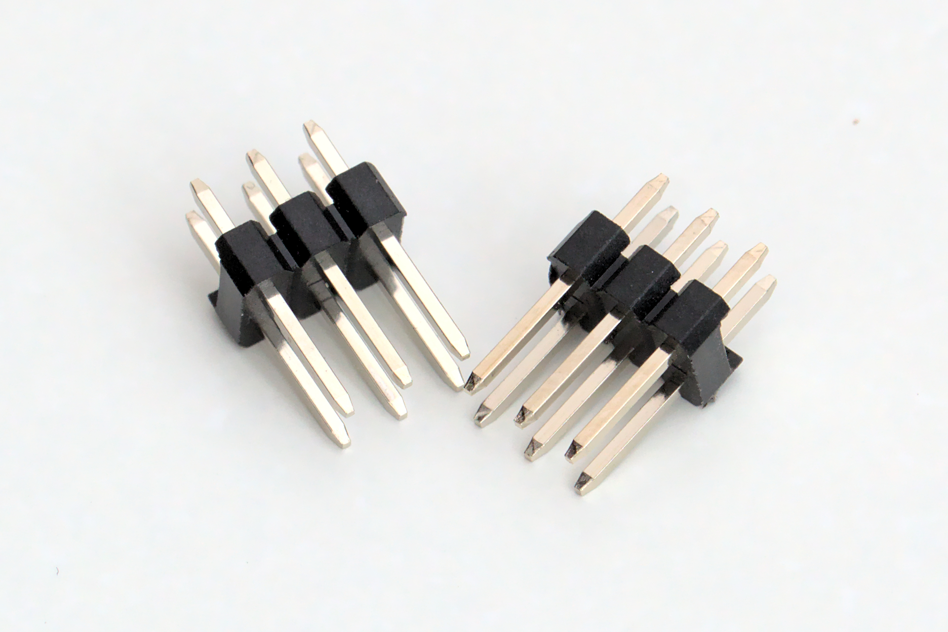
For the solderless version, there will be two 2x3 male PCB Headers that will be used to connect to the breadboard. One trick can be to insert the headers into the breadboard, and place the board over and align in the PCB headers. This can help hold the headers stay in place as you solder them.
I find it the easiest to tack one pin and use that to align the part to the board, then finish up with the rest of the joints.
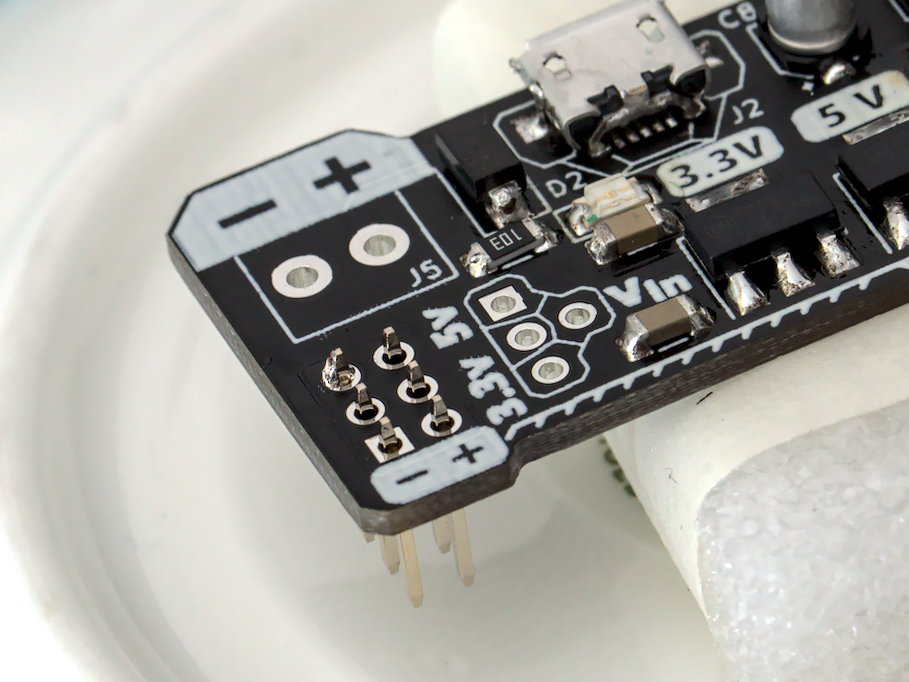
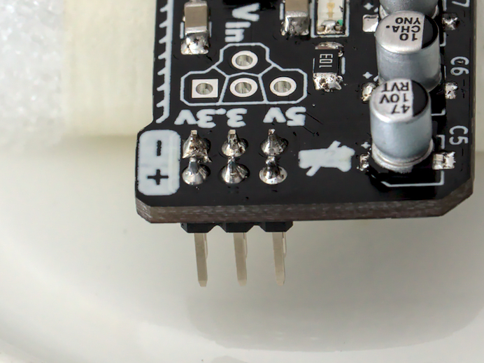
Output Selection Pins
| J8 J9 | XFCN | PZ254V-12-6P |
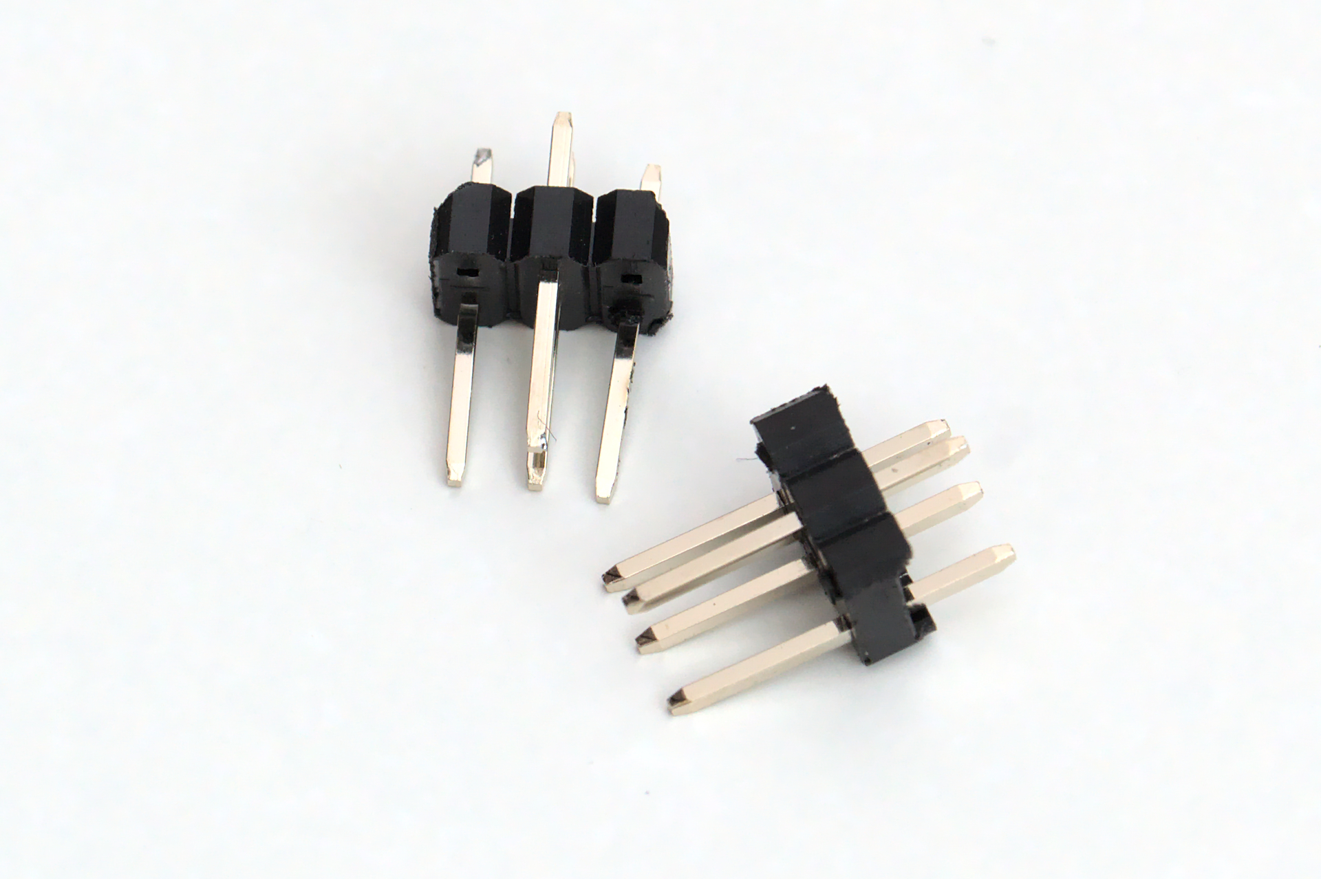
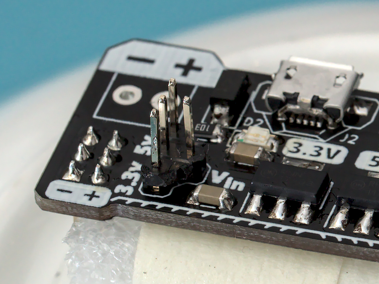
These are just 2x3 male PCB Headers that have had two corner pins taken off to create the unique T shape. This part allows for the output to be selected by rotating a 2 pin jumper.
Make your own Take a pair of snips to chamfer 2 corners, or a soldering iron to heat and pull out two corner pins.
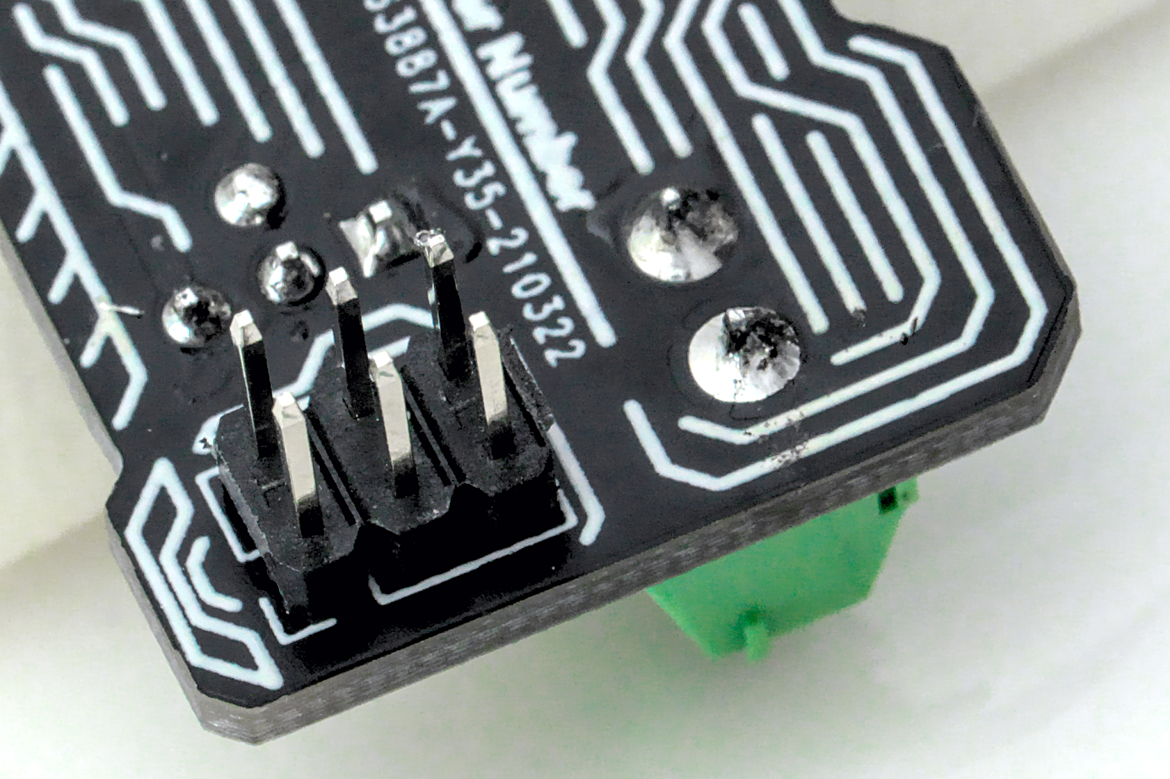
Screw Terminal
| J5 | Ningbo Kangnex Elec | WJ124-3.81-2P |
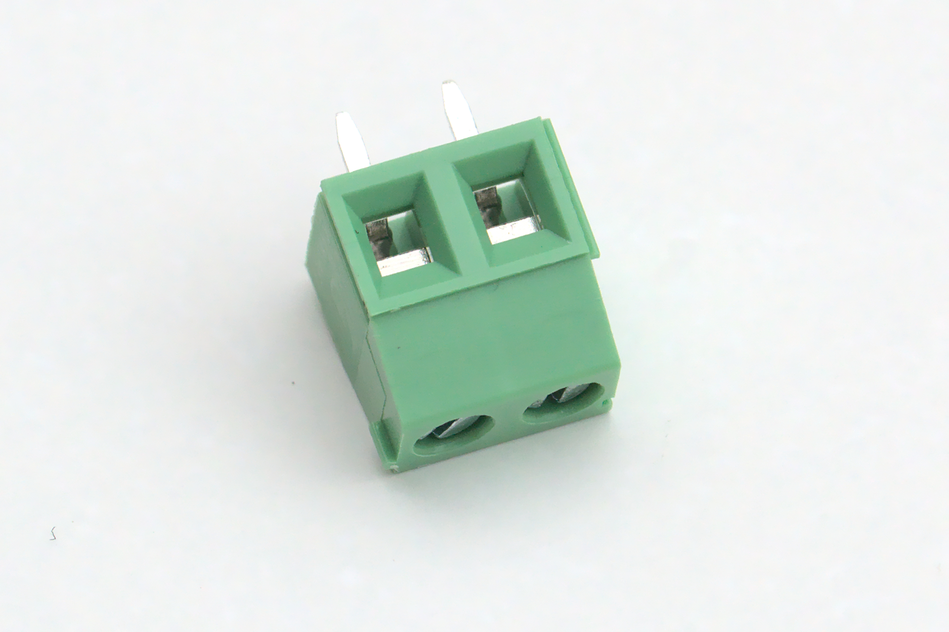
The screw terminal is the largest component on the board, and should be straight forward to mount. Here a larger soldering iron tip and thicker solder will come in handy, but a smaller one will still get the job done.
Cleaning
Double check all the solder joints and touch up any that need some attention. You should clean the board as the last step, so now’s the chance to fix mistakes. (Or you might have to clean the board twice, the horror!)
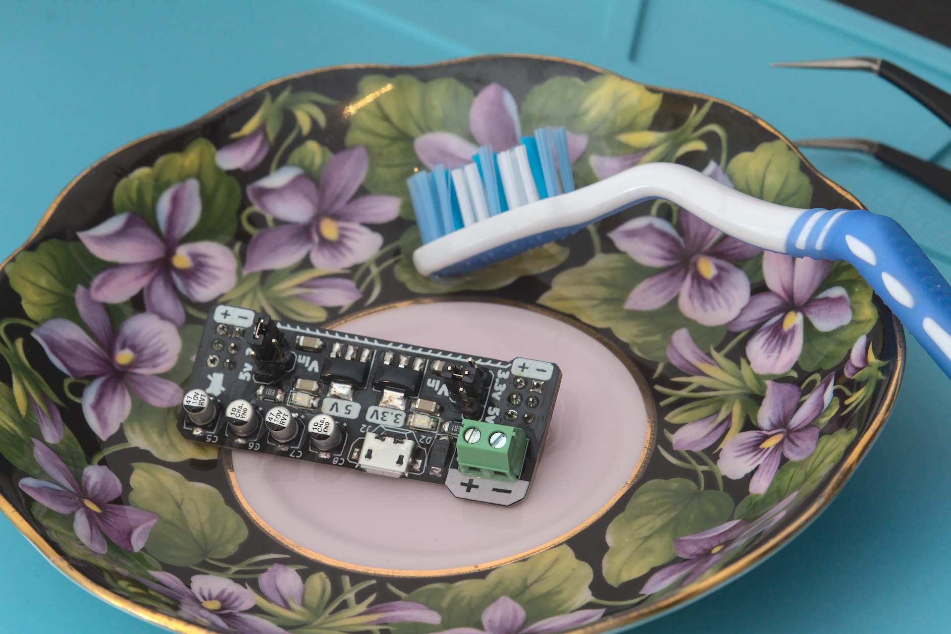
Now that everything is mounted to the board, it deserves a good clean to wash off the flux residue and any other gunk. A tooth brush can make a decent tool to use, and its neck can be bent with some heat from a hot air station.
I use denatured ethenol to clean my boards. Another popular options is to use Isopropyl Alcohol. I have heard about using soap and water, but make sure to double check which options is best for you.
Open Baths of Flamable Gas and Liquid Cleaning with an alcohol based solution will create a fire hazard. Be sure to follow the below safety measures and do so at your own risk.
- Be sure there are no sources of flame or spark nearby.
- Discharge any static charge you may carry.
- Work in an a well ventilated area.
- Wear gloves and splash goggles
If you have an ultrasonic cleaner, check with the manufacturer’s recomendations or your preferred methods.
Testing
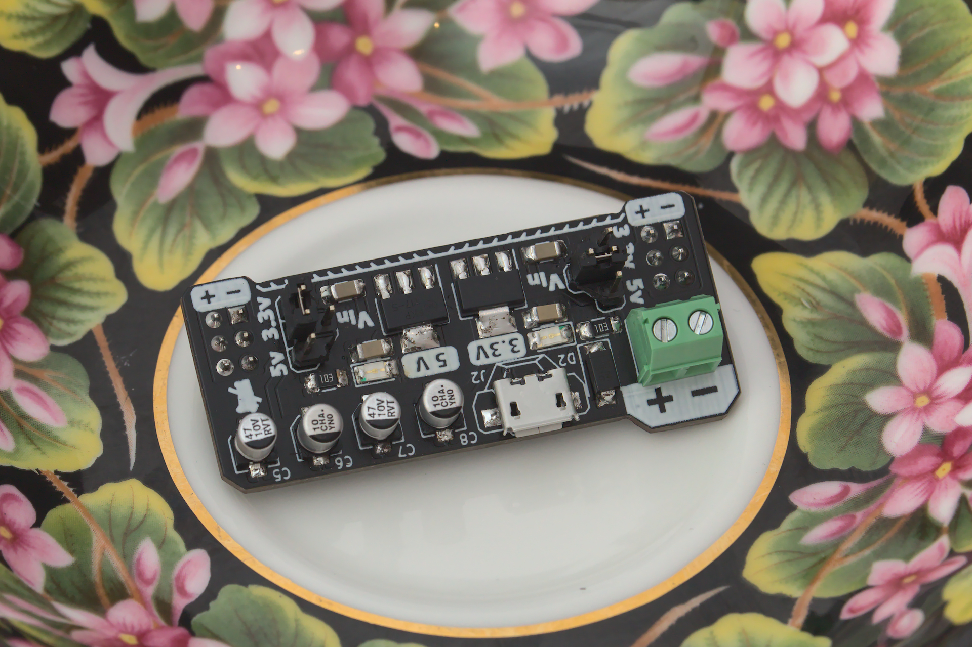
Now that the board is fully mounted and cleaned, it’s time test it out.
Simply plugging in a 5v Micro USB cable into the connector should show both LEDs illuminated. For further testing, a DC voltage (min 5.5V, max 20V) on the screw terminal should also show both LEDs illuminated.
If one or both LEDs are off, check that they are orientated correctly. how to check
Finishing Up
Congratulations on building your own Micro Breadboard Power Supply! I hope the documentation has been useful. If not, let me know and I’ll help fix it!
- Check out the Schematics to read more about how the design works.
- See more photos from the development.
- Fork the source files to modify the design.
- Ready to build your own? Buy yours on Tindie.