Schematics
The schematics for this project are very straight forward. Both the original Micro BBPS and the integrated version share the exact same schematics.
Input Connectors
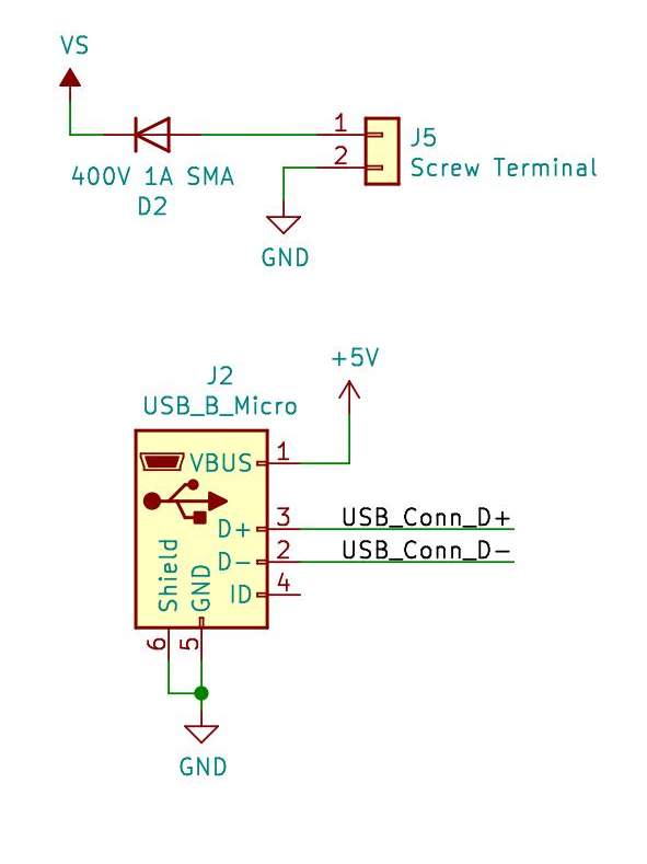
The power entry is handled by both a screw terminal and a Micro USB connector. A diode of appropriate ratings is used to help prevent any reverse polarity connections.
Voltage Regulators
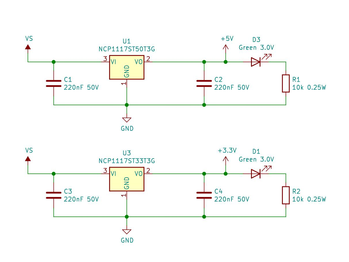
Most of the functionality of the circuit comes into play with the two linear voltage regulators. These offer a 20V maximum and 1 A current limit for each output. Note that the Micro USB’s 5V rail will be on the same side as the output of the 5V regulator. This means that whatever is supplying the power to the Micro USB cable will be what is supplying the 5V rail. This was to make sure that there wasn’t a voltage drop on the 5V output if a 5V source is being applied to the input of the voltage regulator.
Power Filtering
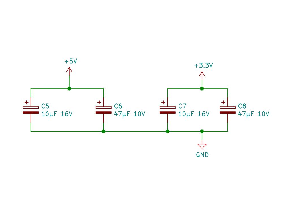
For more filtering, these electrolytic capacitors are included for both the 5V and 3.3V power rails. These will help reduce any dips in voltage as sudden spikes in current will have a place to draw power from beyond just that of the linear regulators.
Output
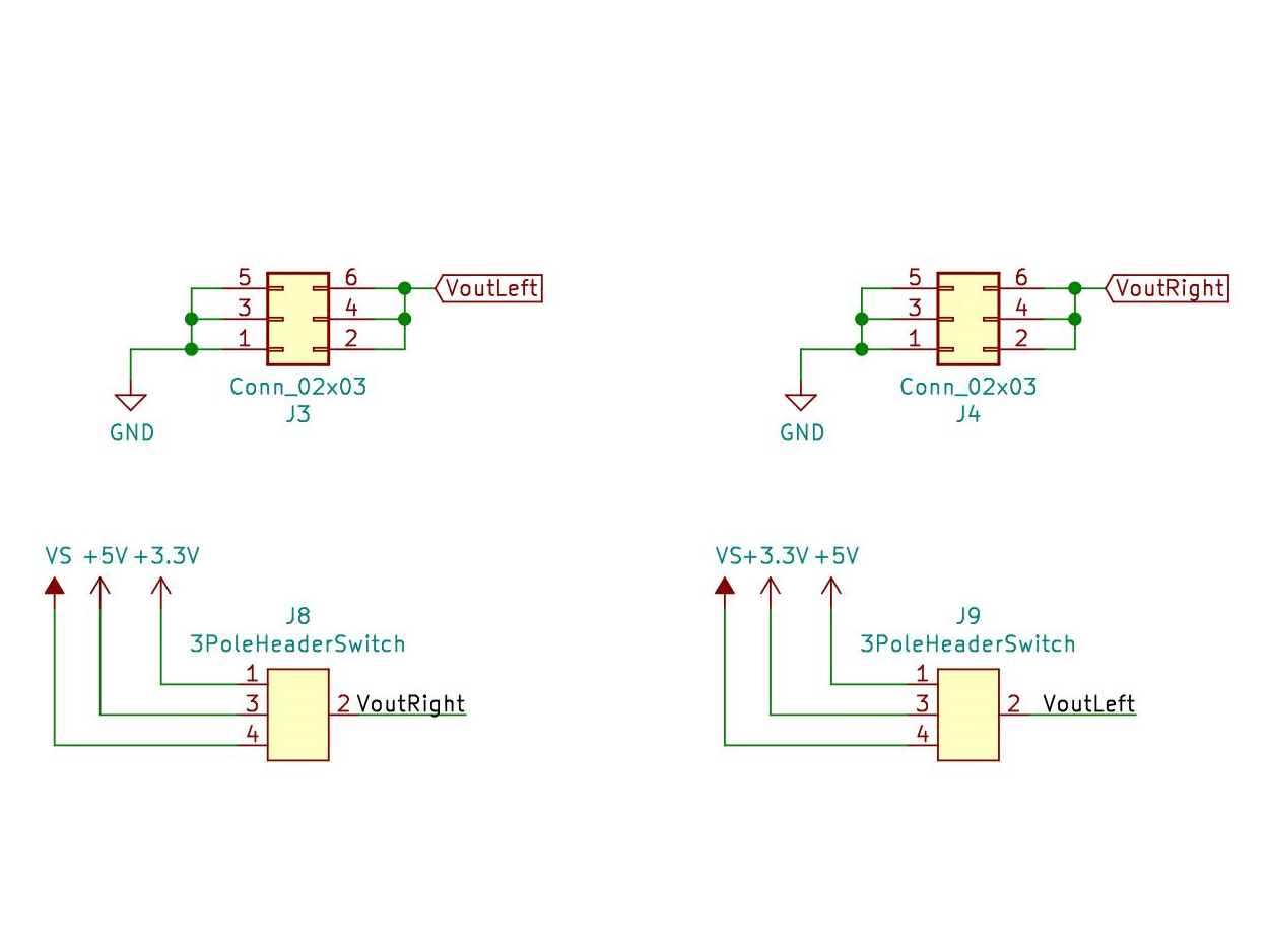
Here we can see the output connectors and the selector switch to set which voltage source is applied to either left or right side.