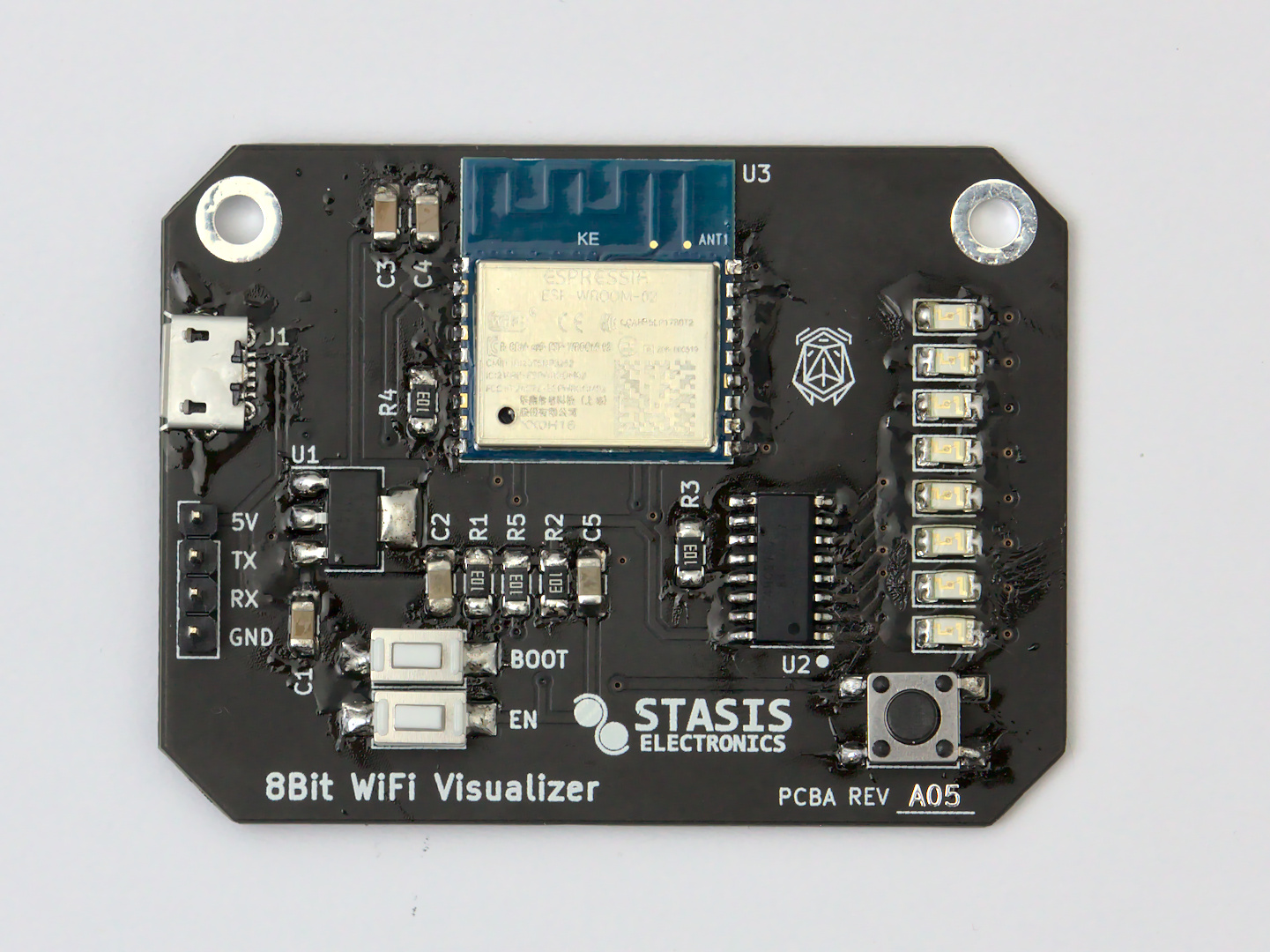
Board Assembly
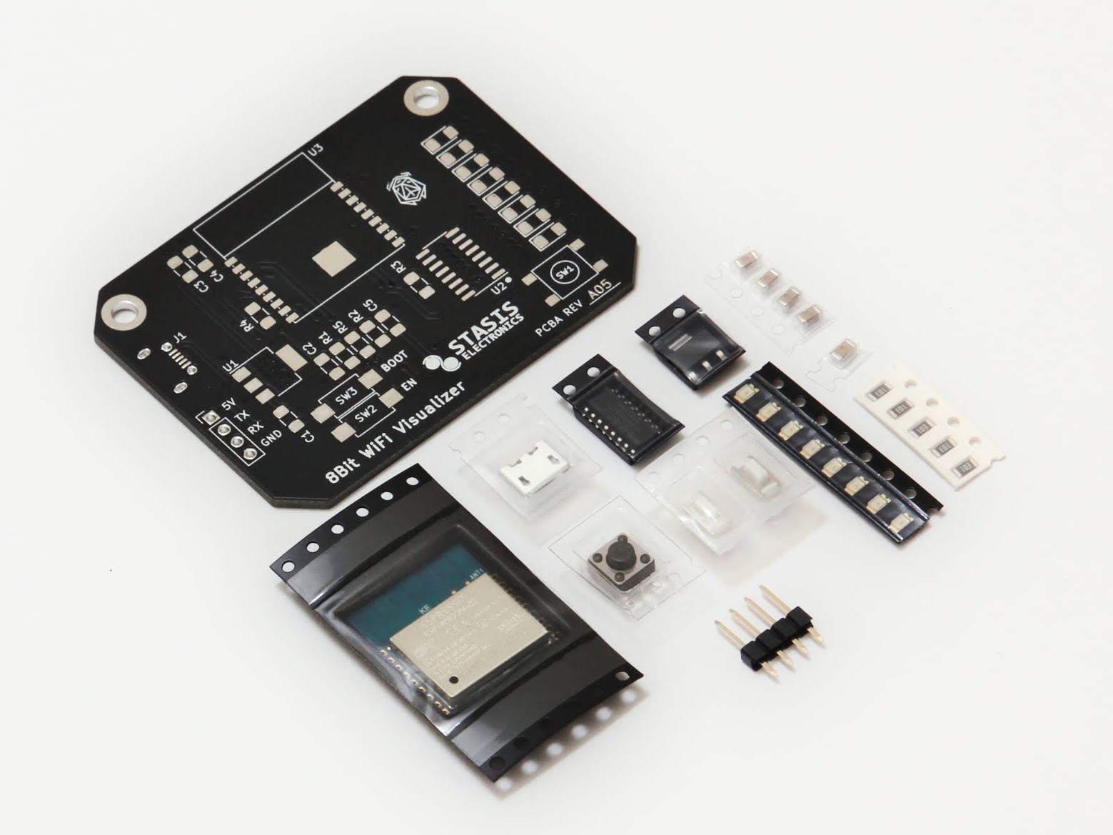
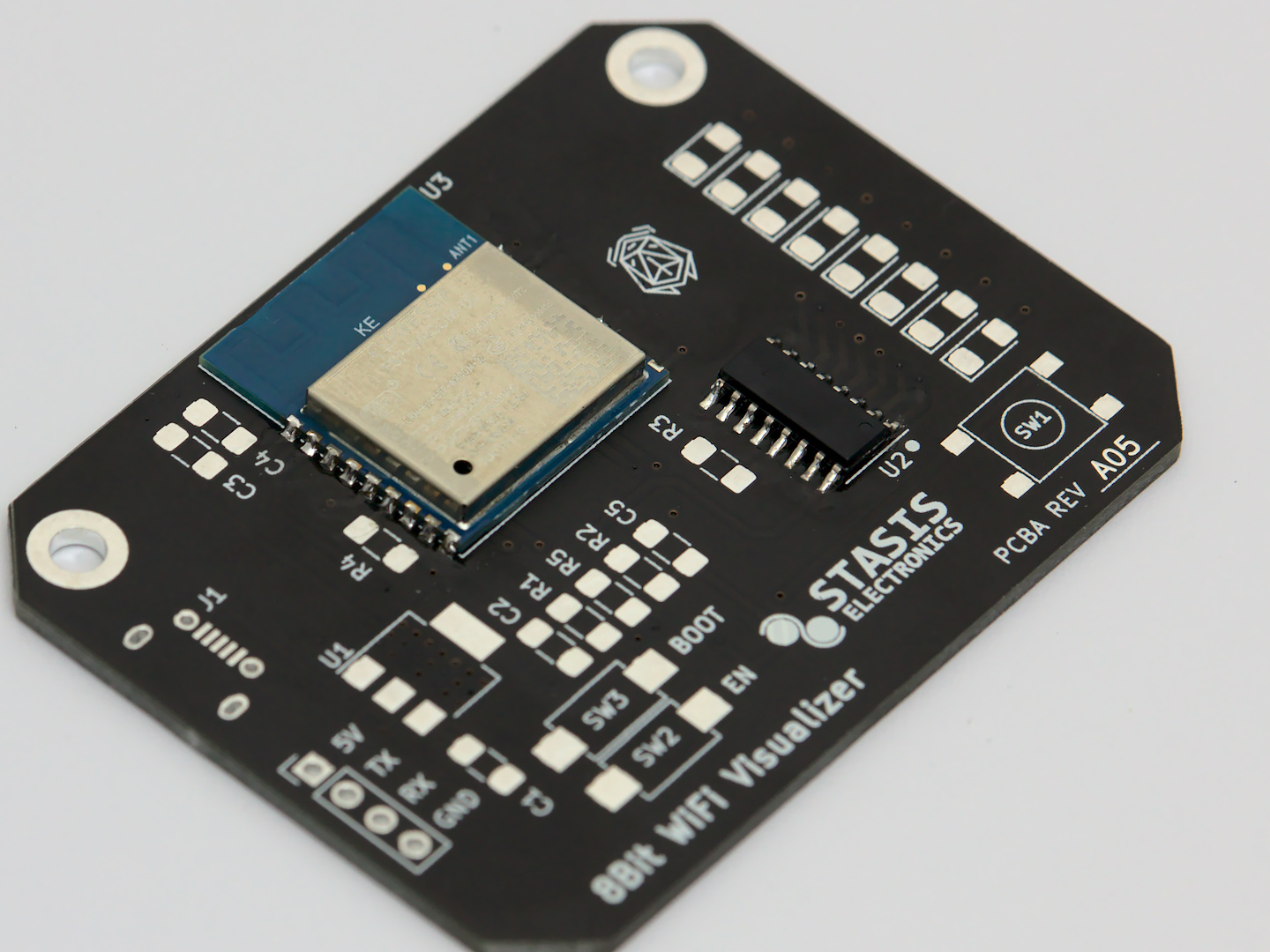
Once you’ve gotten your parts kit opened, it’s time to assemble your very own 8 Bit WiFi Visualizer board!
Tools Needed
Before you begin soldering, make sure to gather your tools. It’s no fun to have your hands tied up and then realize the next tool you need is packed away somewhere (or worse, at the store!).
| Required | |
|---|---|
| Soldering Iron | If you have a soldering iron with a fine tip, that is preferred, however you can make do with a moderately sized tip. |
| Solder | Make sure to have a solder that is thin enough. It should be less than 0.5 mm, with 0.3 mm being ideal. |
| Fine Tip Tweezers | SMD parts are small, make sure you have something that can pick them up and move them around. |
| Flux | Rosin based flux will help make sure all your solder joints are strong and hassle free. |
| Optional | |
|---|---|
| Magnification | Ideally a stereo microscope, but a magnifying glass can be better than no magnifaction. Young eyes help too, but those can’t be bought. |
| Hot Air Station | This makes removing parts a snap if mistakes were made. It can also be used to position parts using the liquid solder’s surface tension. |
| Solder Paste | Using a hot air station with solder paste can make assembly a breeze. |
| Stencil | A piece of metal with holes cut out for where the solder paste can be scraped over. Most PCB fabricators offer stencils for a relatively small fee. |
Using a stencil? Jump to Instructions
Solder the WiFi module
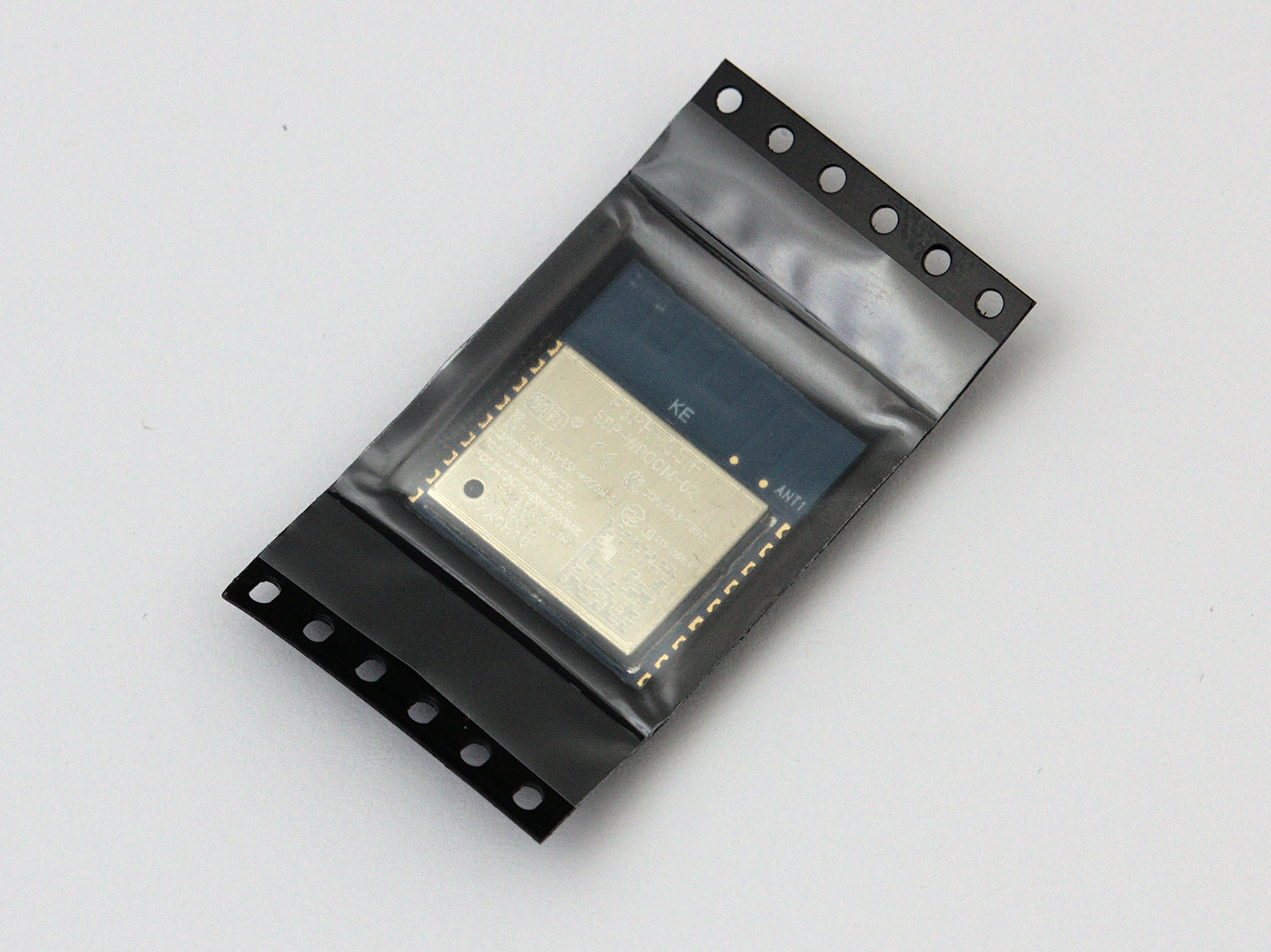
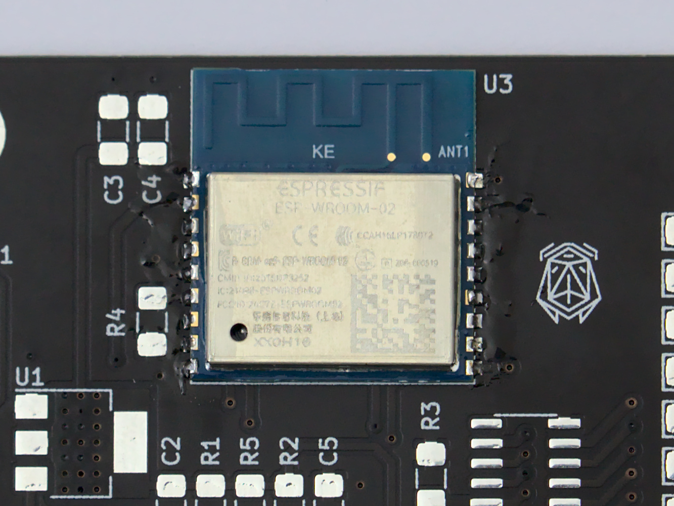
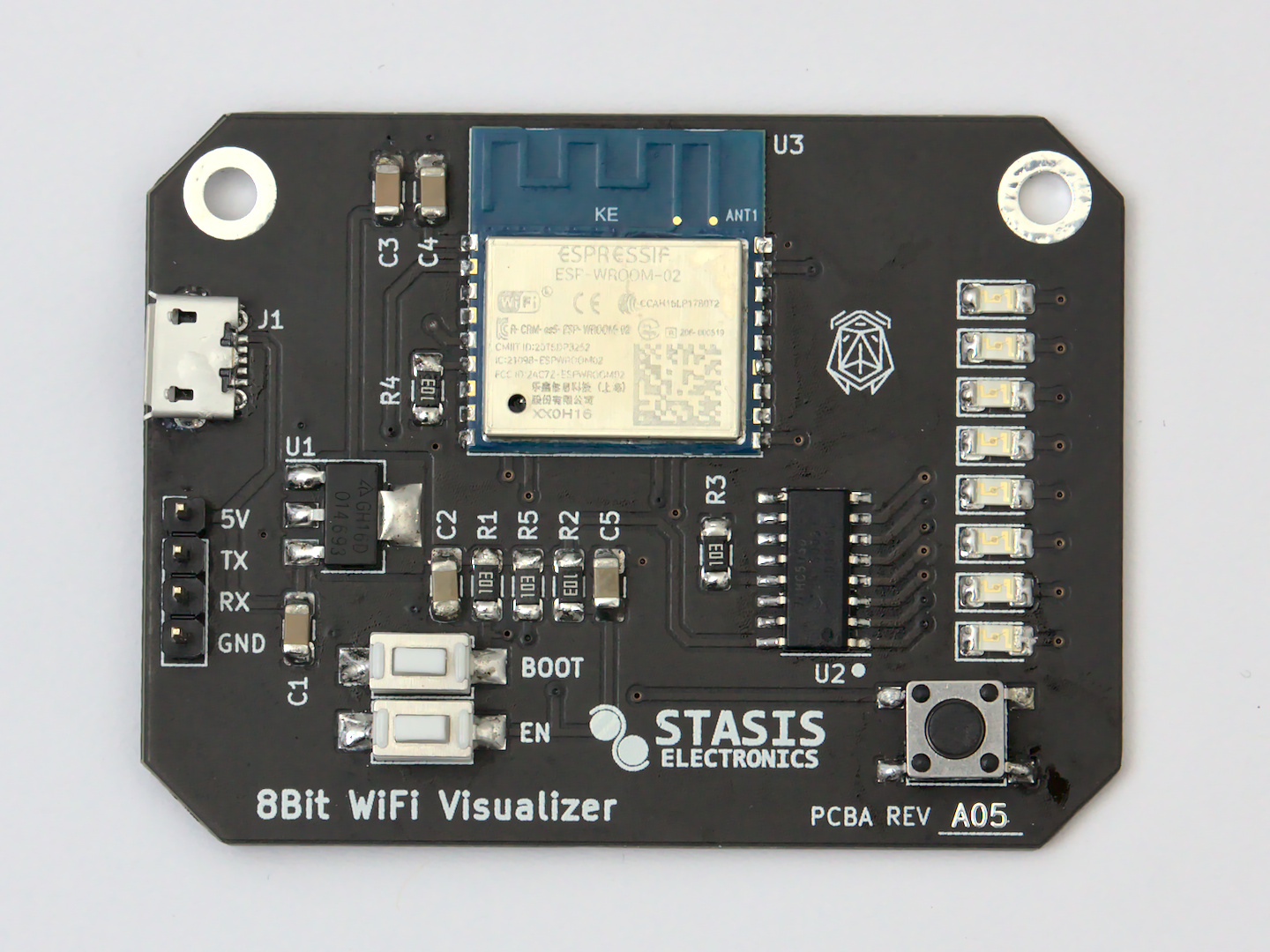
Start off with soldering the ESP-WROOM-02 WiFi module. This will help get the largest device on the board first without any other component getting in the way.
Tape the module down
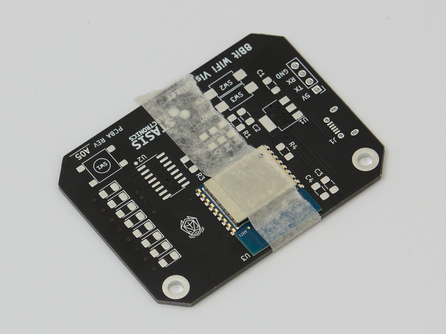
Using masking tape (or other low-tac tape), position the WiFi module so that the castellated pads match up with the pads on the board. You can also use the silkscreen to position the module correctly.
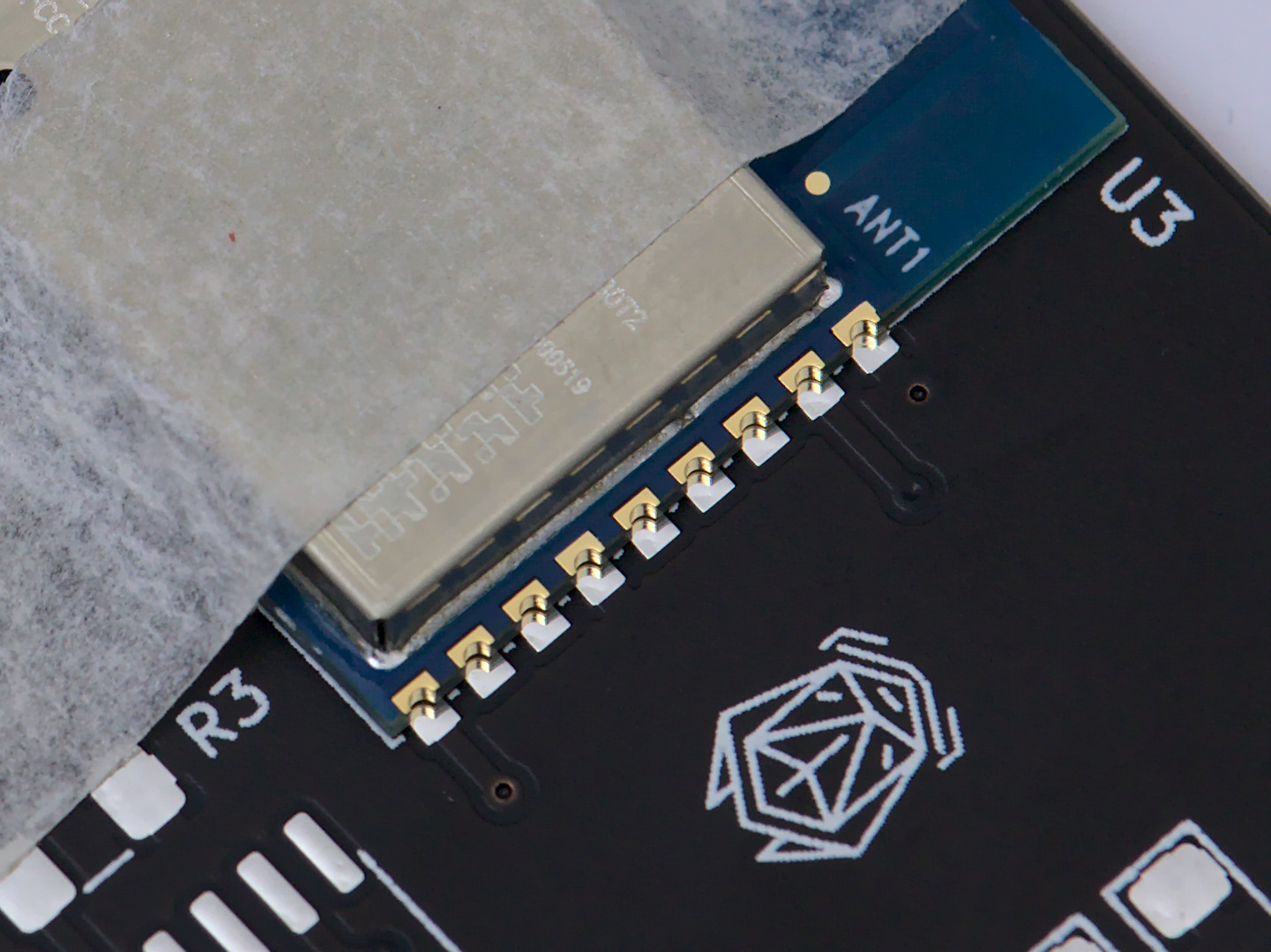
You can have the tape cover one side of the module. Solder the side you can, and the module should be mounted securely enough to remove the tape. Make sure to solder the other side that was previously under the tape.
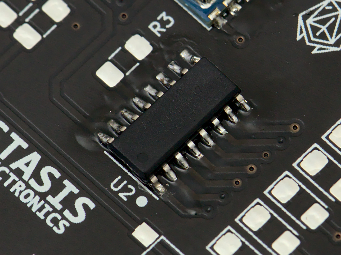
Solder the Shift Register
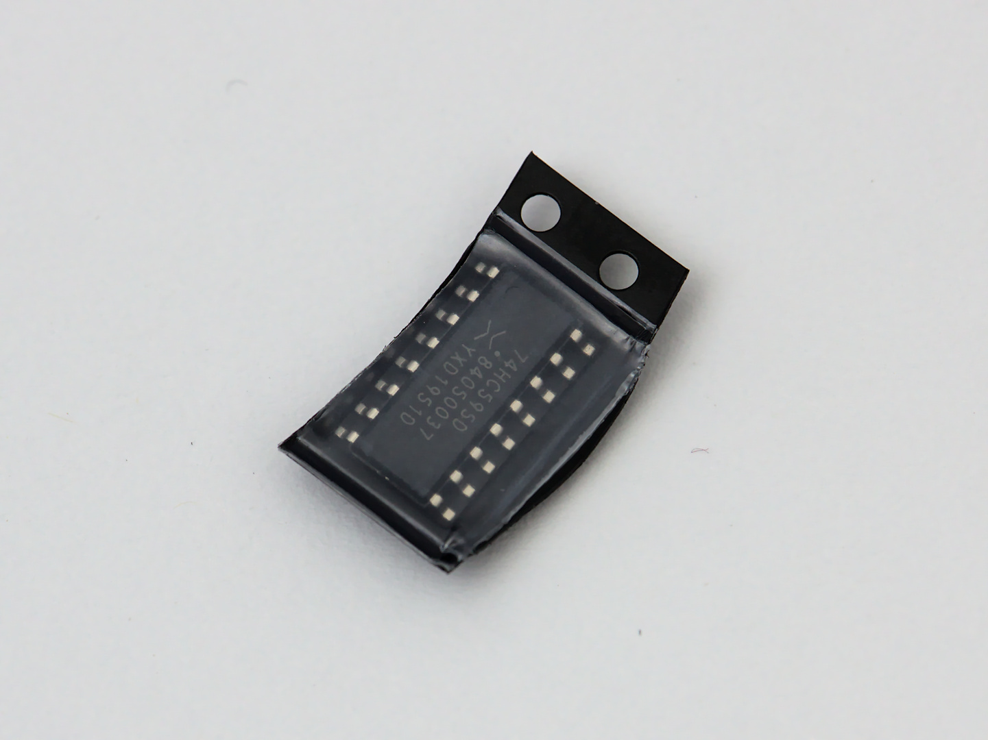
Next up is the shift register U2. Begin by adding solder to one of the corner pads, and while keeping the solder liquid bring the IC onto the footprint and into position.
This device is “upside down” relative to the top of the board. Make sure the IC is correctly positioned with the Pin 1 marking aligned with the white dot on the board.
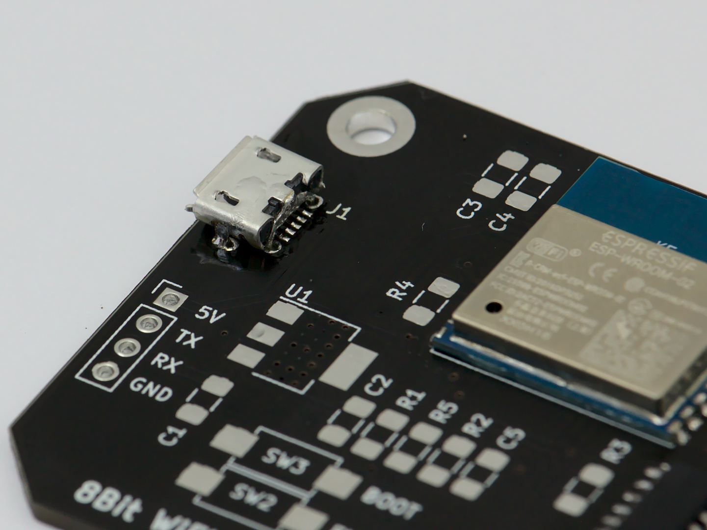
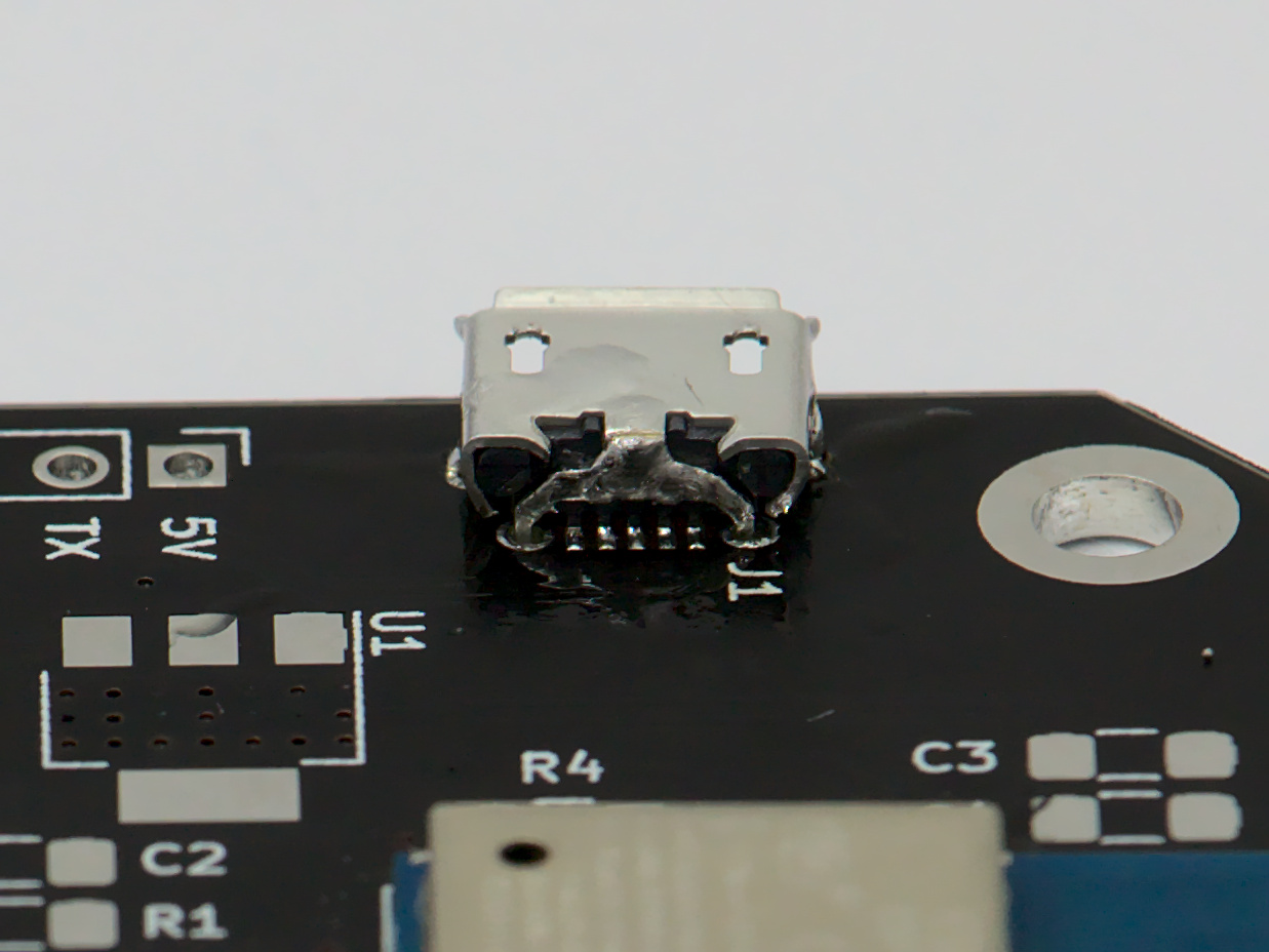
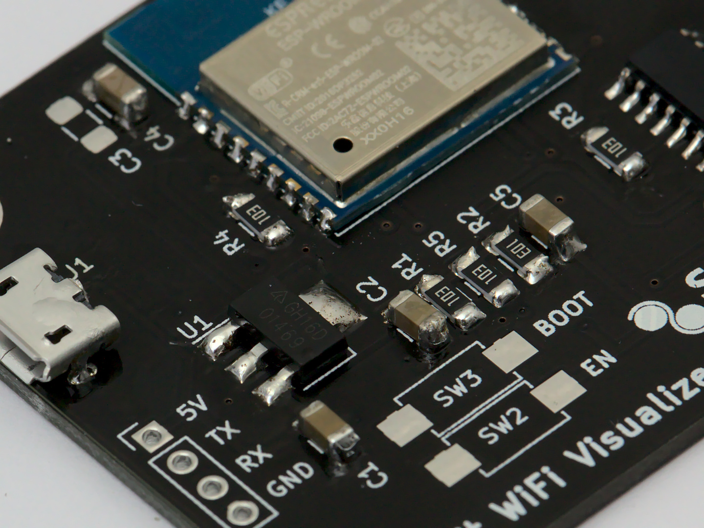
Solder the Micro USB Connector
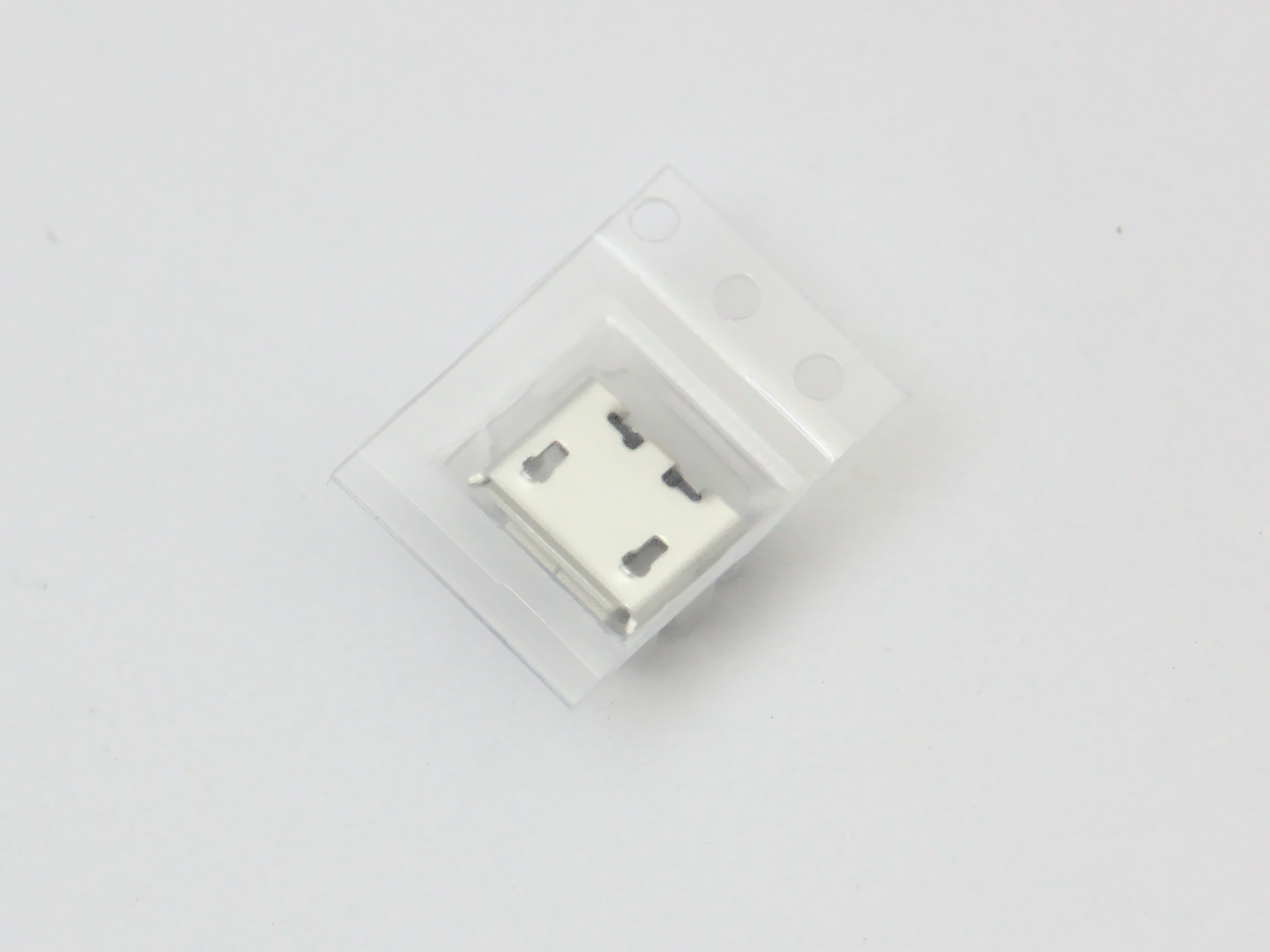
Here is where the flux will really come in handy. The pins on the USB connector are the smallest pads on the board, and will be the hardest.
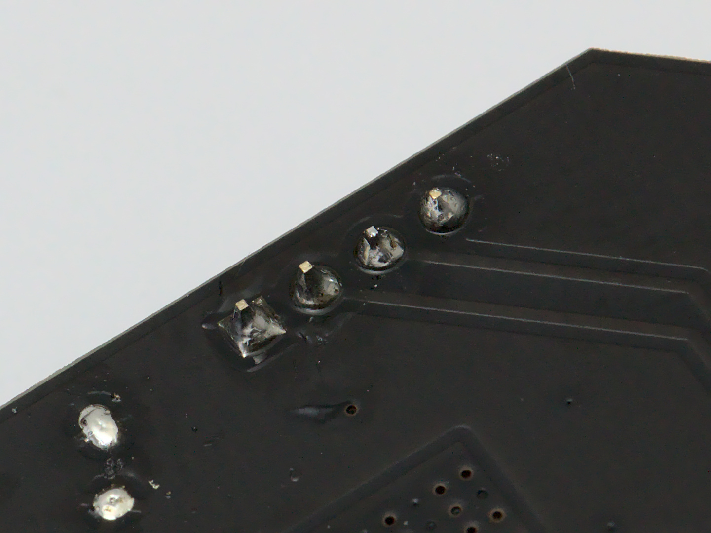
Make sure to add just enough solder on the strain releif through hole pads to add strenght.
If too much solder is added to the strain relief pads, it can make inserting the micro USB cable difficult or even impossible
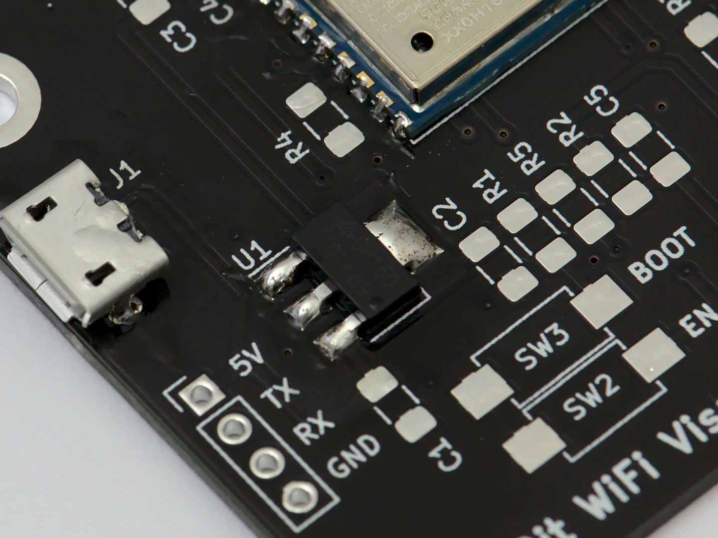
Solder the Voltage Regulator
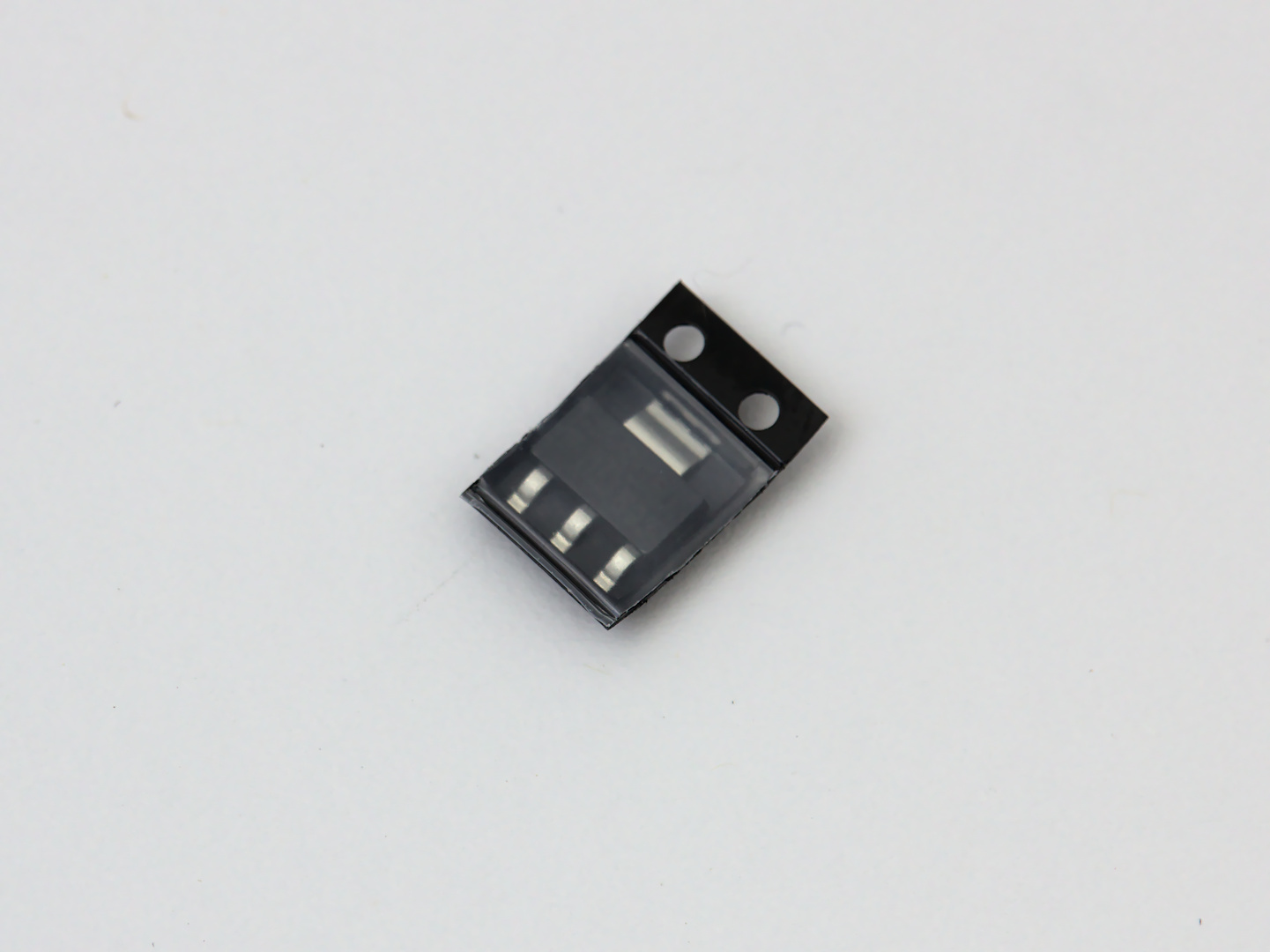
The voltage regulator U1 is up next. This part should be straight forward, as the pins are larger than the others.
Solder the Passives
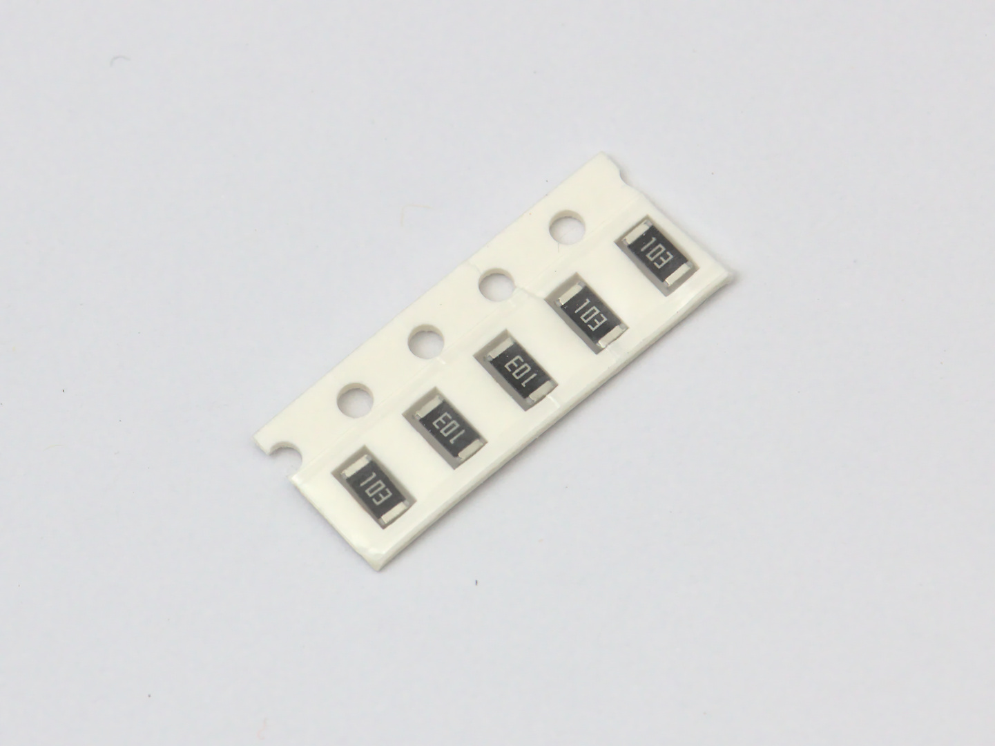
We’re almost there. For all of these parts there is no wrong direction for how they are attached.
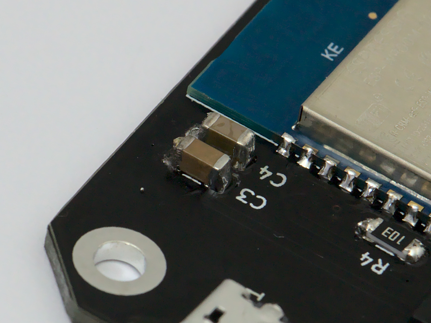
Start with the resistors, which are all the same value: 10 kΩ.
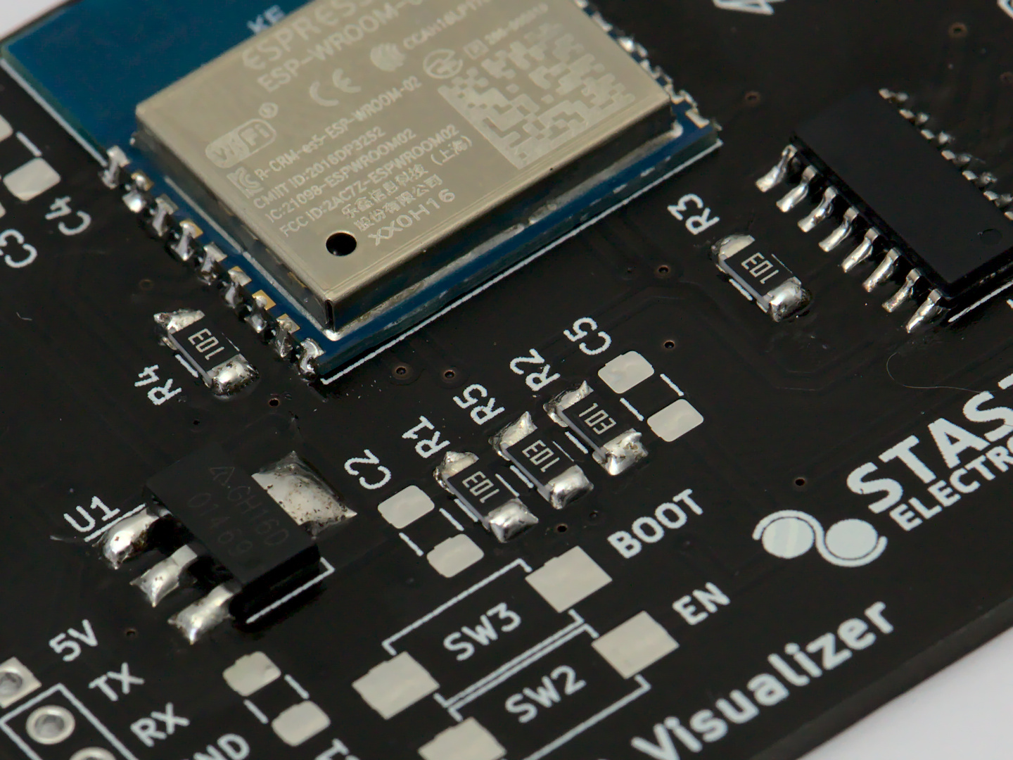
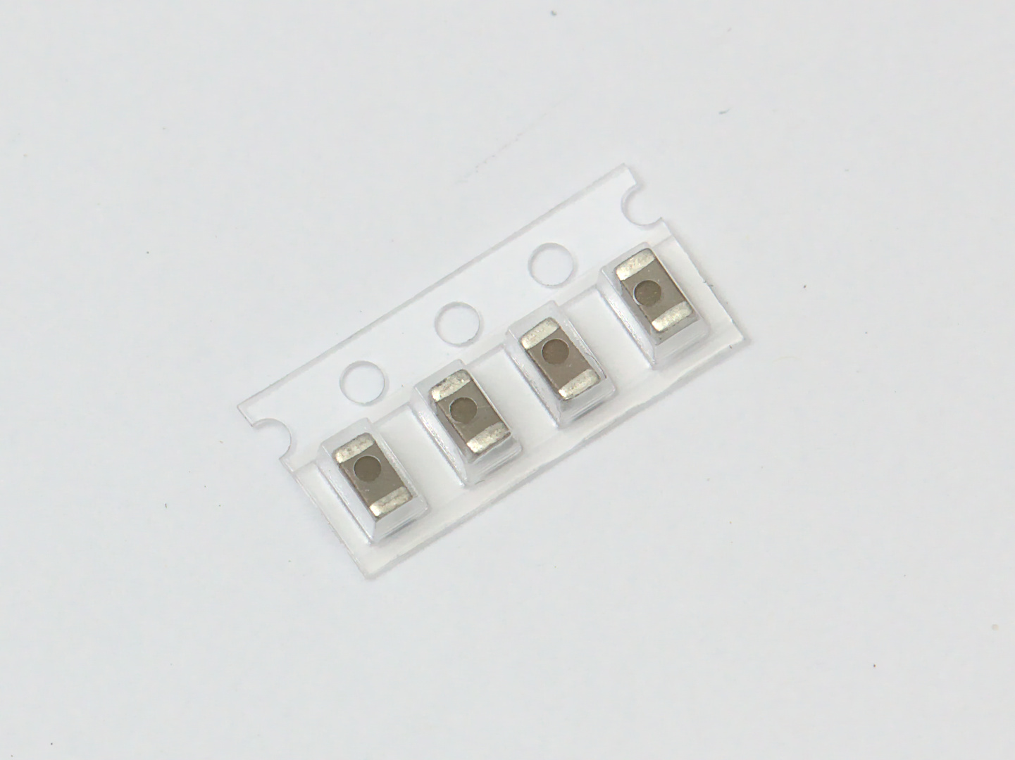
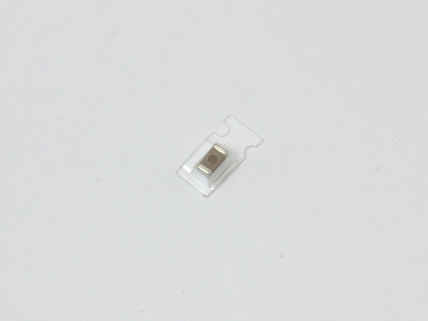
There are four 1μF Capacitors, and one 10μF: C3
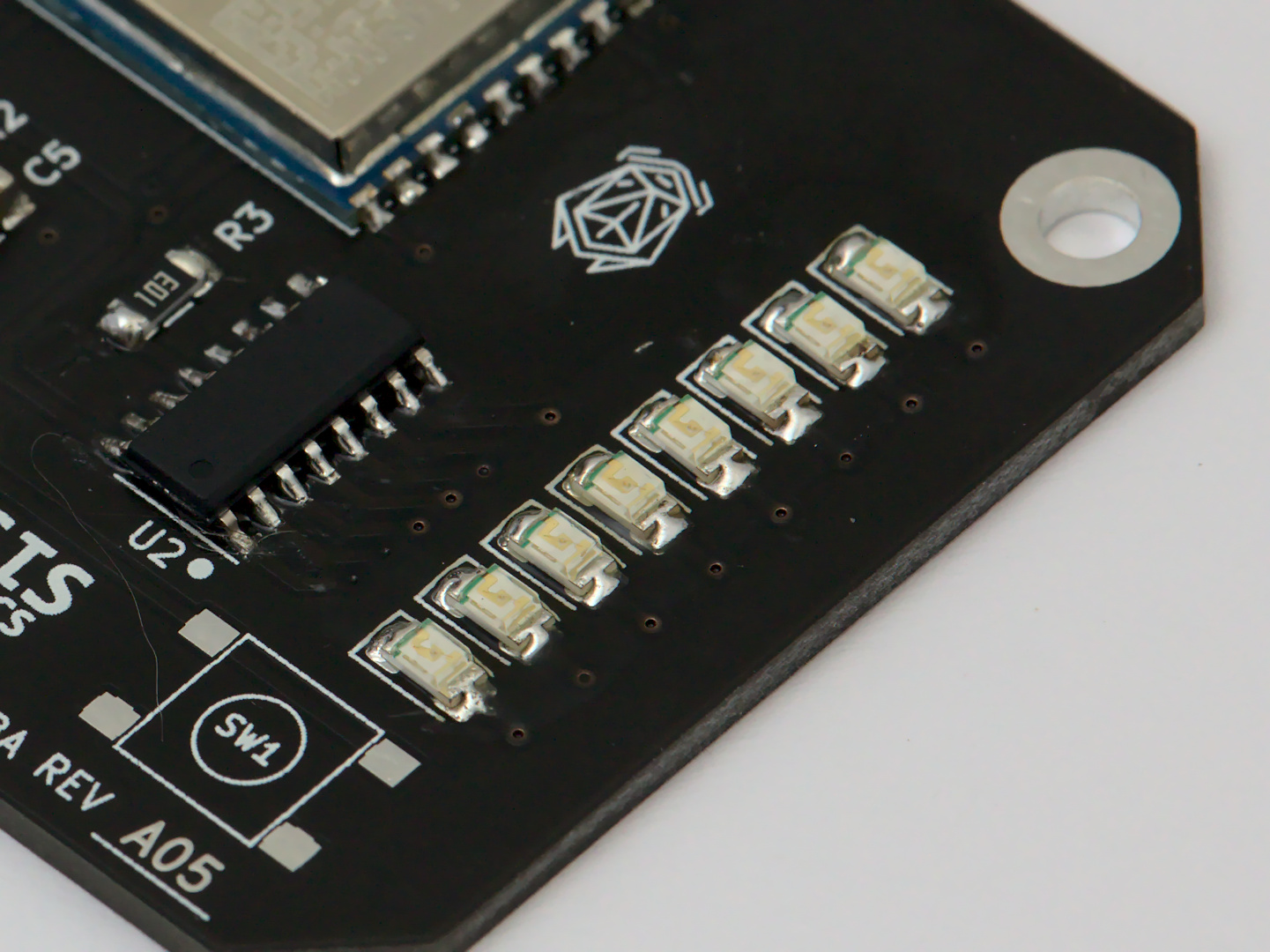
Solder the LEDs
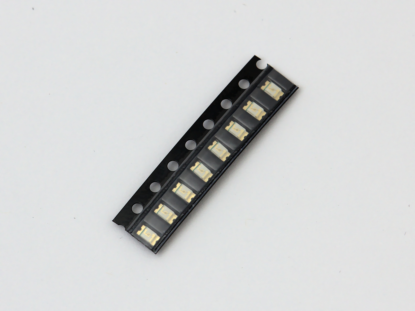
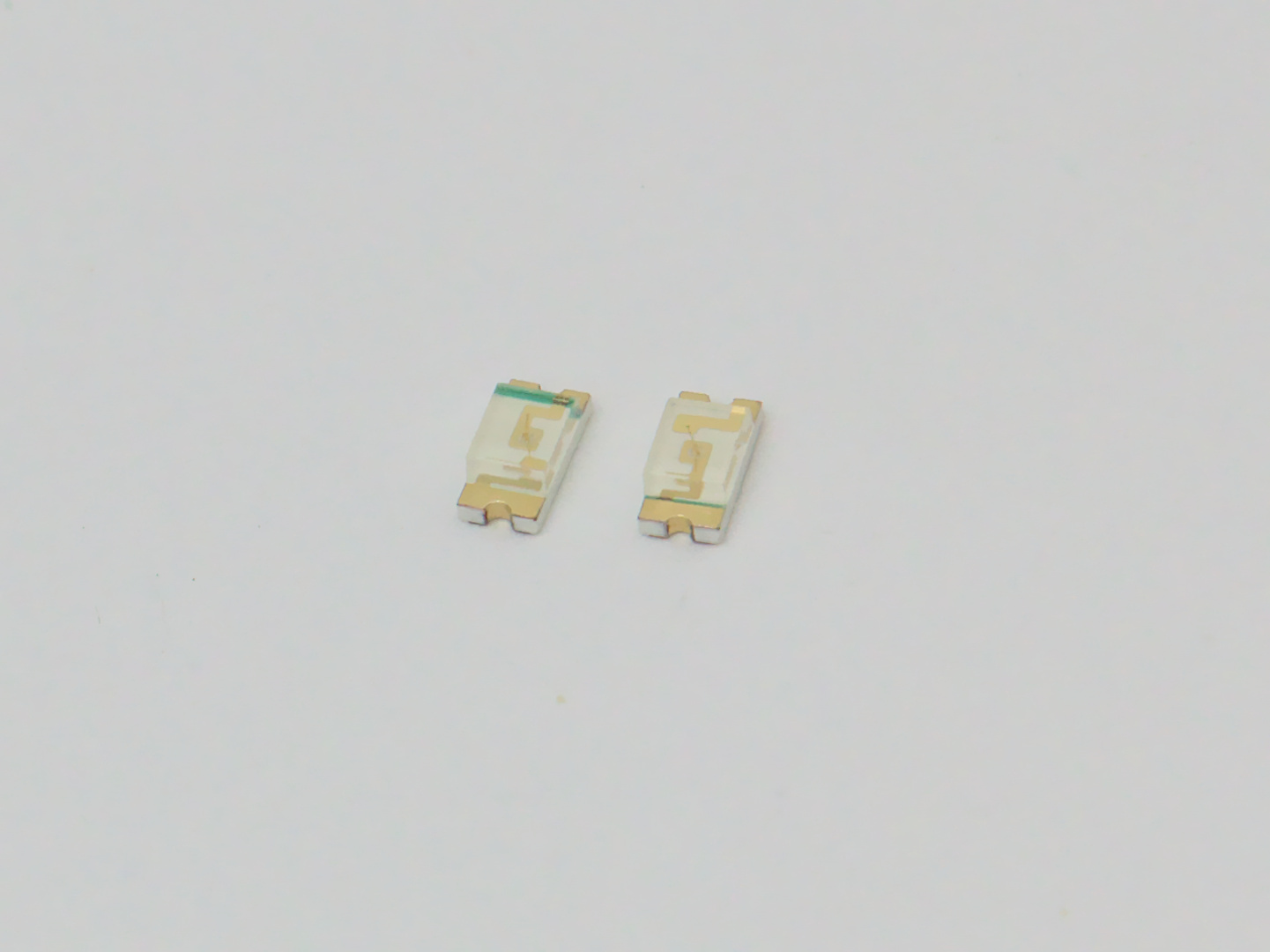
The LEDs are “polarized”, which means they have a right way and a wrong way of being attached to the board.
How to tell which way to attach the LEDs
The LEDs will have a small green line that can be seen at an angle inside the plastic dome of the LED. This marks the anode, or the negative terminal. This green line should be on the side of the footprint with the silkscreen marking.
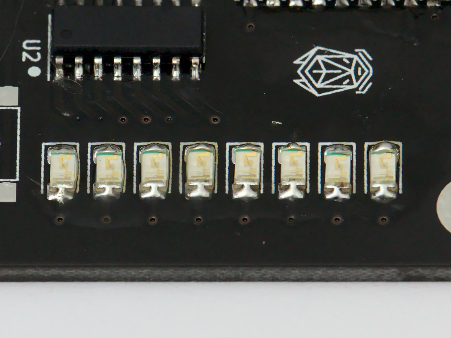
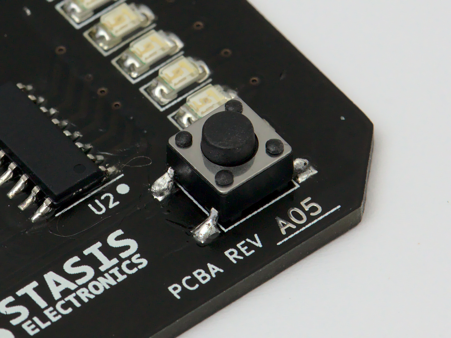
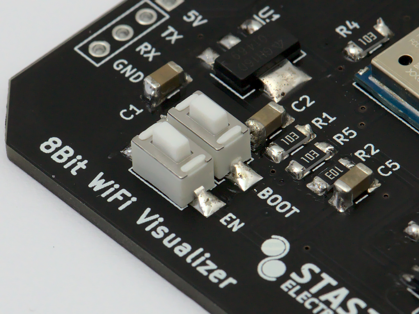
Solder the Buttons
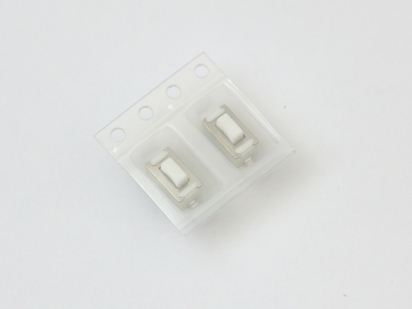
These parts should be pretty straigh forward. They don’t have a specifc direction.
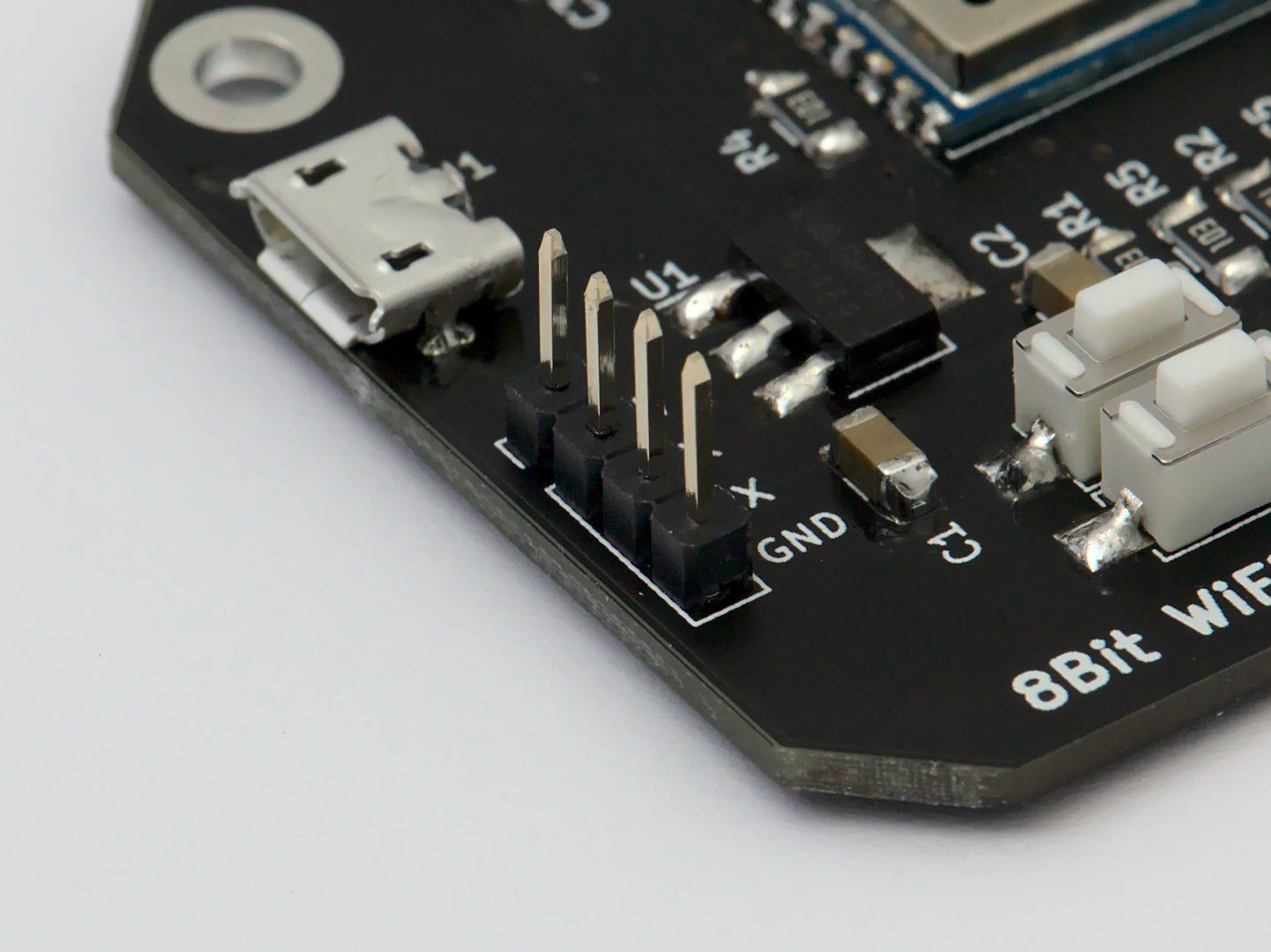
Solder the PCB Headers
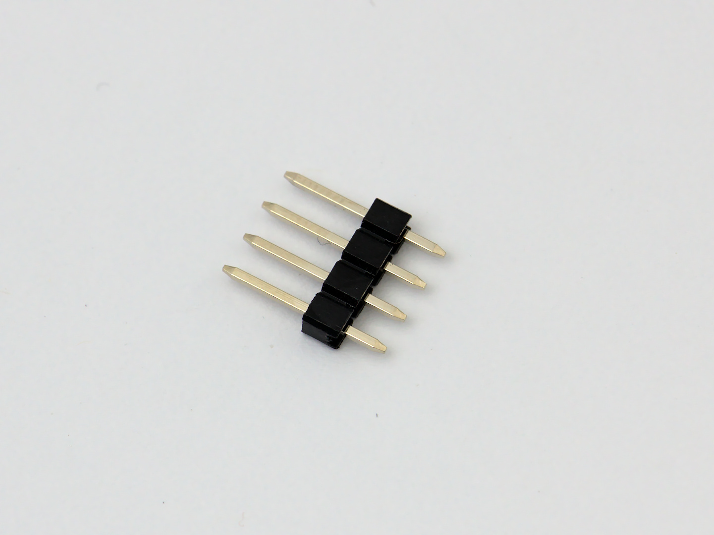
This will be the 4 pin PCB header used to load new Arduino sketches to the ESP-WROOM-02 module, and read any debug messages on the serial terminal.
Cleaning Up
After all that soldering and flux, it’s time to give the board a quick clean. If you have a preferred cleaning agent, go ahead and use that. Some common ways of cleaning PCBs is to use an alcohol like isopropyl or denatured alcohol. I use denatured alcohol, since it is cheaper than isopropyl.
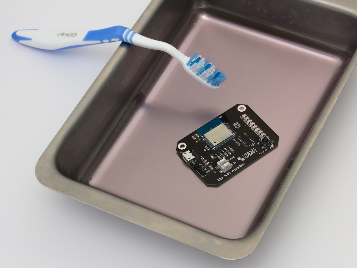
A toothbrush makes a good tool to get inbetween all the nooks and crannies of the parts on the board. I’ve used the hot air station to heat up the neck of the toothbrush to bend it to be more comfortable to use.
Using a Stencil
If you have a stencil made by your PCB fabricator, (or maybe you have a way of fabricating your own!). You can use that to quickly apply solder paste to the pads and get things soldered real quick.
Chances are that if you are using a stencil, this board is not your first time.
The general process is to position the stencil so that it is flush against the PCB and the stencil aligns perfectly with the pads.
Scrape the solder paste
Using a hard piece of plastic or metal, scrape solder paste across all the holes in the stencil with as few movements as possible. Make sure all pads have solder paste on them.
Place SMD Components
If you’re using a hot air station to heat the board up, avoid placing the buttons. The plastic in the buttons can melt under the heat of a hot air station.
Heat until the solder flows
Using the hot air station, apply heat to a small area of the board. Focus on one area at a time, looking for the solder paste to liquefy and become shiny.
Hand Solder remaining Components
If you left the buttons to hand solder, now is the time to add them.
Attach the PCB Headers so that you can upload new Arduino sketches to the ESP-WROOM-02 WiFi module.